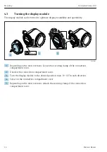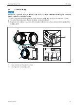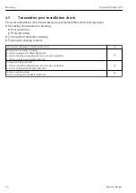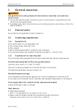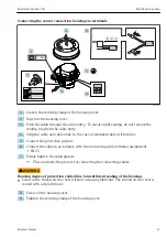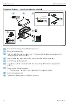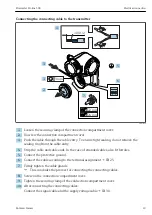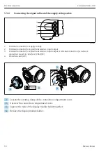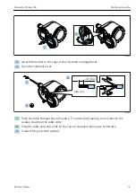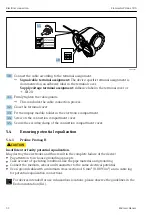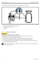
Electrical connection
Flowmeter Proline 500
20
Hauser
5.2.4
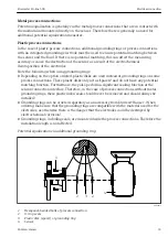
Terminal assignment
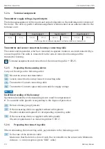
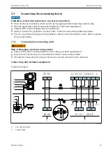
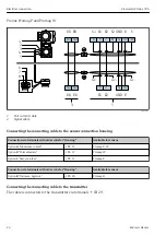
Transmitter: supply voltage, input/outputs
The terminal assignment of the inputs and outputs depends on the individual order version of
the device. The device-specific terminal assignment is documented on an adhesive label in the
terminal cover.
Supply voltage
Input/output 1
Input/output 2
Input/output 3
1 (+)
2 (–)
26 (+)
27 (–)
24 (+)
25 (–)
22 (+)
23 (–)
Device-specific terminal assignment: adhesive label in terminal cover.
Transmitter and sensor connection housing: connecting cable
The sensor and transmitter, which are mounted in separate locations, are interconnected by a
connecting cable. The cable is connected via the sensor connection housing and the
transmitter housing.
Terminal assignment and connection of the connecting cable → 25.
5.2.5
Preparing the measuring device
Carry out the steps in the following order:
1. Mount the sensor and transmitter.
2. Sensor connection housing: Connect connecting cable.
3. Transmitter: Connect connecting cable.
4. Transmitter: Connect signal cable and cable for supply voltage.
NOTICE
Insufficient sealing of the housing!
Operational reliability of the measuring device could be compromised.
‣
Use suitable cable glands corresponding to the degree of protection.
1. Remove dummy plug if present.
2. If the measuring device is supplied without cable glands:
Provide suitable cable gland for corresponding connecting cable.
3. If the measuring device is supplied with cable glands:
Observe requirements for connecting cables → 17.
5.2.6
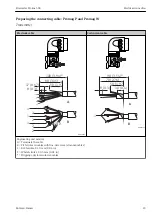
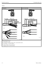
Preparing the connecting cable
When terminating the connecting cable, pay attention to the following points:
1. In the case of the electrode cable:
Make sure that the ferrules do not touch the core shields on the sensor side. Minimum
distance = 1 mm (exception: green “GND” cable)
Summary of Contents for Flowmeter Proline 500
Page 47: ......

