Diagnostics and troubleshooting
Liquipoint FTW33
30
Hauser
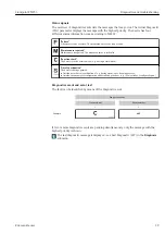
12.3.2 Overview of diagnostic events
Status
signal/
Diagnos-
tic event
Diagnostic
behavior
IO-Link
EventQualifier
EventCode Event text
Reason
Corrective measure
F270
Fault
IO-Link
Error
0x5000
Defect in electronics/
sensor
Electronics/sensor defective
Replace device
S804
Warning
IO-Link
Warning
0x1801
Load current > 200
mA
Load current > 200 mA
Increase load resistance at
switch output
Overload at switch
output 2
Overload at switch output 2
• Check output wiring
• Replace device
C485
Warning
IO-Link
Warning
0x8C01
Simulation active
When the simulation of a switch
output or current output is
active, the device displays a
warning.
Switch off simulation
C182
Message
IO-Link
Message
0x1807
Invalid calibration
Switch point/switchback point
are too close together or inter-
changed.
• Check probe coverage
• Perform configuration again
C103
Message
IO-Link
Message
0x1813
Sensor check failed
Sensor check failed
• Repeat cleaning
• New calibration recommen-
ded and check switching
behavior
• Replace device
-
Message
IO-Link
Message
0x1814
Sensor check passed
Sensor check
-
-
Information
IO-Link
Information
0x1815
Timeout Reedcontact
Timeout reed contact
Remove test magnet
S825
Warning
IO-Link
Warning
0x1812
Ambient temperature
outside of specifica-
tion
Ambient temperature outside of
specification
Operate device in the specified
temperature range
1)
EventCode as per IO-Link standard 1.1
12.4 Behavior of the device in the event of a fault
The device displays warnings and faults via IO-Link. All the device warnings and faults are
for information purposes only and do not have a safety function. The errors diagnosed by
the device are displayed via IO-Link in accordance with NE107. Depending on the
diagnostic message, the device behaves as per a warning or fault condition. A distinction
must be made between the following types of error here:
• Warning:
– The device continues measuring if this type of error occurs. The output signal is not
affected (exception: simulation is active).
– The switch output remains in the state defined by the switch points.
• Fault:
– The device does
not
continue measuring if this type of error occurs. The output signal
assumes its fault state (switch outputs de-energized).
– The fault state is displayed via IO-Link.
– The switch output changes to the "open" state.
12.5 Resetting to factory settings (reset)
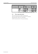
Reset to factory settings (RES)


