Installation
Micropilot FMR56, FMR57 FOUNDATION Fieldbus
34
Hauser
If process temperatures are high, the device must be included in normal tank insulation to
prevent the electronics heating up as a result of heat radiation or convection. The
insulation may not exceed beyond the neck of the housing.
6.5
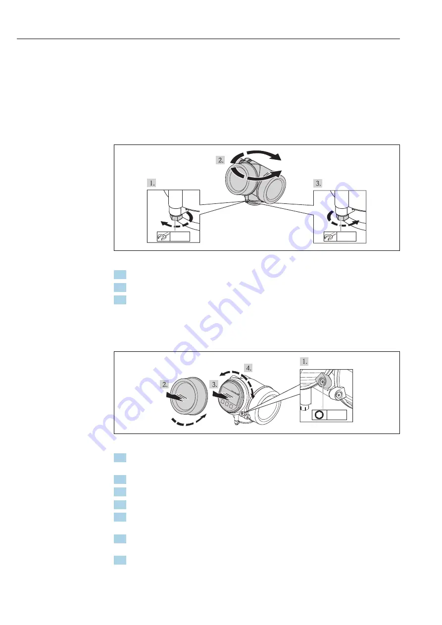
Turning the transmitter housing
To provide easier access to the connection compartment or display module, the transmitter
housing can be turned:
max. 350°
8 mm
8 mm
A0013713
1. Unscrew the securing screw using an open-ended wrench.
2. Rotate the housing in the desired direction.
3. Tighten the securing screw (1,5 Nm for plastics housing; 2,5 Nm for aluminium or
stainless steel housing).
6.6
Turning the display module
+
E
–
1
3 mm
A0013905
1. If present: Loosen the screw of the securing clamp of the electronics compartment
cover using an Allen key and turn the clamp 90° conterclockwise.
2. Unscrew cover of the electronics compartment from the transmitter housing.
3. Pull out the display module with a gentle rotation movement.
4. Rotate the display module into the desired position: Max. 8 × 45 ° in each direction.
5. Feed the spiral cable into the gap between the housing and main electronics module
and plug the display module into the electronics compartment until it engages.
6. Screw the cover of the electronics compartment firmly back onto the transmitter
housing.
7. Tighten the securing clamp again using the Allen key (Torque: 2.5 Nm).
Summary of Contents for Micropilot FMR56
Page 197: ......
Page 198: ...www addresses endress com 71344036 71344036 ...


