background image

BA00387C/07/EN/13.12
71162645

Operating Instructions

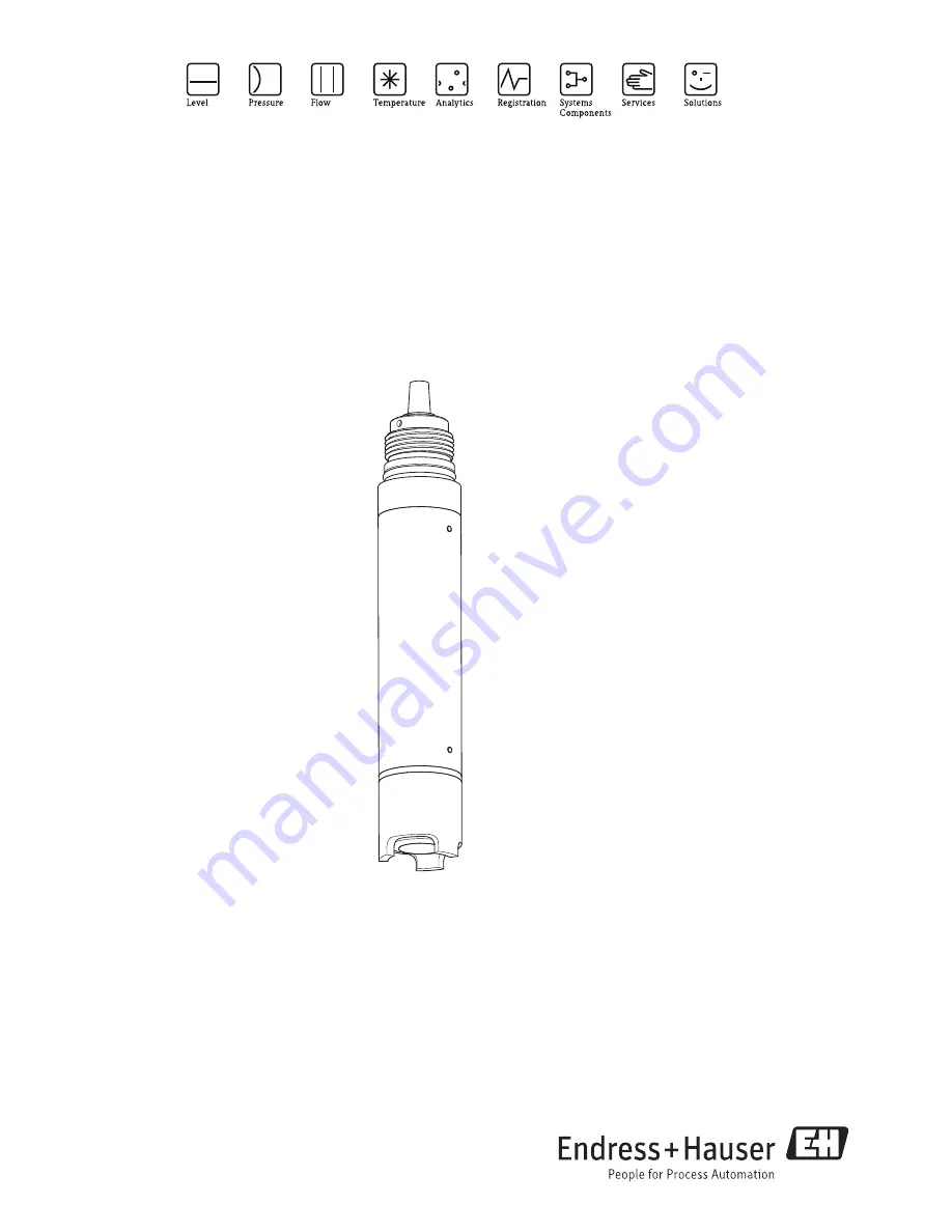
Oxymax COS61

Dissolved oxygen sensor

Summary of Contents for Oxymax COS61

Page 1: ...BA00387C 07 EN 13 12 71162645 Operating Instructions Oxymax COS61 Dissolved oxygen sensor...

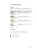
Page 2: ...age is not heeded Corrective action This symbol alerts you to a dangerous situation Failure to avoid the situation can result in a fatal or serious injury CAUTION Cause consequences Consequences if sa...

Page 3: ...he transmitter 15 4 2 Connection via junction box 16 4 3 Post connection check 16 5 Device description 17 5 1 Sensor design 17 5 2 Measuring principle 18 5 3 Calibration 18 6 Commissioning 21 6 1 Func...

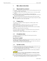
Page 4: ...s and the entire measuring system and is not permitted The manufacturer is not liable for damage caused by improper or non designated use 1 3 Occupational safety As the user you are responsible for co...

Page 5: ...s Hauser 5 1 5 Product safety The product is designed to meet state of the art safety requirements has been tested and left the factory in a condition in which it is safe to operate Relevant regulatio...

Page 6: ...his product 3 The configurator opens in a separate window Use the radio buttons to configure the order code from the nameplate of your device 4 Afterwards you can export the order code as a PDF or Exc...

Page 7: ...aged products until the matter has been settled Check that the order is complete and agrees with your shipping documents The packaging material used to store or to transport the product must provide s...

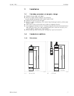
Page 8: ...lling sensors You will find them in the Operating Instructions for the assembly used 3 2 3 Mounting location Select the installation location so that there is easy access for later calibration Make su...

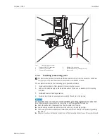
Page 9: ...pension assembly if used into the process NOTICE No assembly used sensor not correctly installed grounding regulations not observed Risk of damaging the sensor cable no protection to electromagnetic i...

Page 10: ...assembly practically rules out vibrations from the upright post A good self cleaning of the fluorescence cap is reached due to the swinging of the assembly According to this effect the sensor life ti...

Page 11: ...channels is to secure the device to an upright post and a securely mounted immersion tube If the flow is very strong a second transverse pipe can be installed with its own pipe support a0013513 Fig 7...

Page 12: ...e is a floating body COA 110 50 available 9 a0013693 Fig 8 Basin rim mounting 1 Pendulum holder CYH112 2 Assembly Flexdip CYA112 3 Float of assembly CYA112 4 Oxymax sensor a0004108 en Fig 9 Floating b...

Page 13: ...Permissible and impermissible sensor installation positions 1 Ascending pipe best position 2 Horizontal pipe sensor top down impermissible due to air cushion or foam bubble forming 3 Horizontal pipe i...

Page 14: ...ll the assembly at places where air cushions or foam bubbles can be formed or where suspended particles can settle on the sensor membrane or optics 12 3 5 Post installation check Sensor and cable unda...

Page 15: ...ect the sensor directly to the transmitter by using the special measuring cable with SXP plug 4 1 2 Panel mounting Remove the SXP connector transmitter side from the cable Refer to the following table...

Page 16: ...cifications Remarks Are the sensor assembly junction box or cable damaged Visual inspection Electrical connection Remarks Does the supply voltage of the transmitter match the specifications on the nam...

Page 17: ...emitter and detector Fluorescence cap Protection basket Alternatively to the protection basket you can use a spray head COR 3 optional see Accessories for use in immersed operation with cleaning func...

Page 18: ...ed in the sensor In addition to the standard values of concentration saturation index and partial pressure the sensor also returns a raw measured value in s The value corresponds to the decay time of...

Page 19: ...zero point 5 3 2 Calibration intervals You can determine the intervals with the following method 1 Check the sensor one month after its being put into operation Remove the sensor from the medium Clean...

Page 20: ...12 75 16 61 9 85 26 79 8 11 36 97 6 83 6 43 12 42 17 63 9 64 27 81 7 96 37 99 6 72 7 45 12 11 18 64 9 45 28 82 7 82 38 100 6 61 8 46 11 81 19 66 9 26 29 84 7 69 39 102 6 51 9 48 11 53 20 68 9 08 30 86...

Page 21: ...nnections are correctly fitted Do not install the assembly in the process if you cannot make the correct connection reliably 6 2 Calibration The sensor is calibrated at the factory A new calibration i...

Page 22: ...Recalibration if desired or required 7 1 Cleaning The measurement can be corrupted by sensor fouling or malfunction e g Buildup on the fluorescence cap cause longer response times and a reduced slope...

Page 23: ...nal sealing rings 7 2 2 Replacing the fluorescence cap The typical operating life of a fluorescence cap is more than 2 years The sensor checks whether the cap is aging and issues a warning via the tra...

Page 24: ...on tube Ordering acc to product structure see Technical Information TI035C 07 en Flow assembly COA250 For sensor installation in pipe lines PVC Ordering acc to product structure Online configurator ww...

Page 25: ...ng system for COSXX Connection 6 8 mm or 6 35 mm Materials POM V4A Order numbers 6 8 mm 71110801 6 35 mm 71110802 Compressor For cleaning system 230 V AC order number 71072583 115 V AC order number 71...

Page 26: ...P 68 connection humidity or dirt in plug Cleaning of the TOP 68 plug in connection by using cleaning alcohol Temperature display clearly too low Check sensor if necessary send sensor in for repair Dis...

Page 27: ...to follow certain procedures when handling returned products that are in contact with medium To ensure swift safe and professional device returns please read the return procedures and conditions on t...

Page 28: ...0 5 of measuring range end Lifetime of the sensor cap 2 years under reference operating conditions protect against direct sun light 10 3 Environment Ambient temperature range 20 to 60 C 0 to 140 F St...

Page 29: ...tion 0 3 kg 0 66 lbs Materials Process connection G1 Sensor cable shielded 7 core fixed cable or double shielded coaxial cable with 4 pilot wires with TOP68 plug connection Maximum cable length max 10...

Page 30: ...llation 15 Floating body 12 Flow operation 13 Fluorescence cap 18 23 I Immersion assembly 24 Immersion operation 10 Incoming acceptance 7 Ingress protection 28 Input 28 Installation 7 8 Angle of 8 Che...

Page 31: ...erials 23 Sensor cable 29 Sensor cap 28 Spare parts 27 Storage 7 Storage temperature 28 T Technical data 28 Environment 28 Input 28 Mechanical construction 29 Performance characteristics 28 Process 28...

Page 32: ...BA00387C 07 EN 13 12 FM10...

Reviews: