


Installation
Oxymax W COS61
10
Hauser
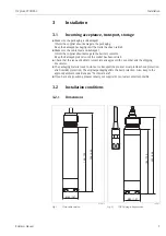
3.4
Installation examples
3.4.1
Immersion operation
Universal assembly holder and chain assembly
For large basins, where sufficient installation distance is required from the basin edge (activated
sludge basin, especially), it is advisable to use the upright post and chain assembly (
6). The free swinging of the immersed assembly practically rules out vibrations from the upright
post.
A good self-cleaning of the fluorescence caps is reached due to the swinging of the assembly.
According to this effect, the sensor life time can be extended.
a0004103-en
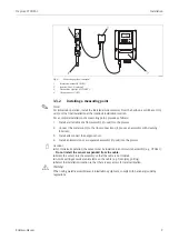
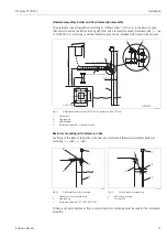
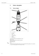
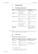
Fig. 5:
Universal assembly holder CYH101 with
immersible pendulum assembly CYA611
1
Weather protection cover
2
Upright post, square pipe SS 1.4301 (AISI 304)
3
Transverse pipe SS 1.4301 (AISI 304)
4
Star handle
5
Second fixing possibility for transverse pipe
6
Immersion assembly CYA611
a0004104-en
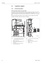
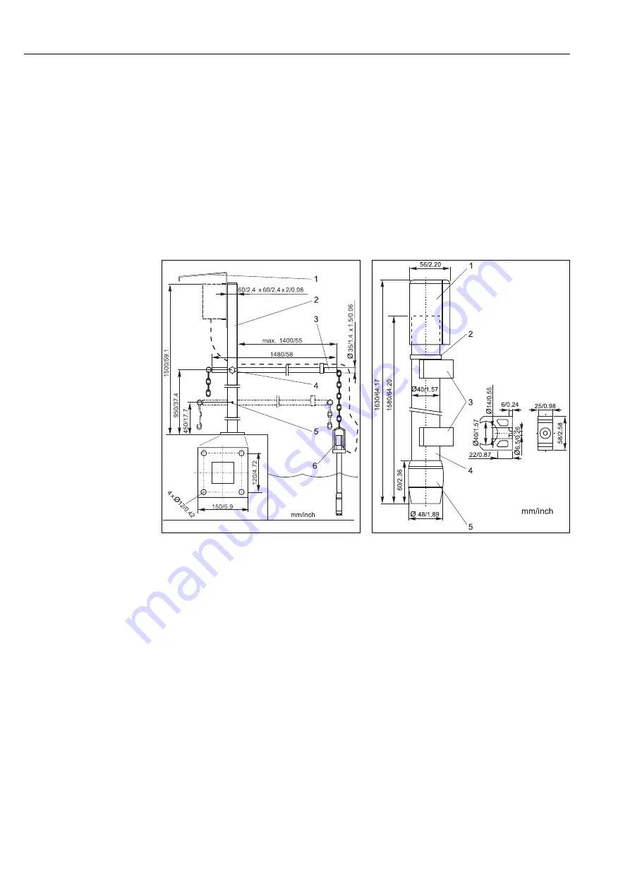
Fig. 6:
Immersible pendulum assembly CYA611
1
Protection cap
2
Worm drive hose clip
3
Pipe clips (detailed drawing in right half)
4
PVC pipe
5
Threaded coupling


