61
Optional fittings
6. Then secure all locks by turning the lock with the square wrench anti-clock-
wise to the stop.
7. Switch the circuit breaker for the POWERLOCK BOX to position “1” or “ON”.
The consumer is securely connected and can be operated.
NOTICE!
If one of the plug connections or the lock cannot be locked, one of the pre-
vious plug connections has not been locked properly.
► Turn each plug connector to the stop before inserting the next one.
► Never turn the main switch back on before all plug connectors and the lock
have been properly locked.
To undo the POWERLOCK connection, perform the steps in reverse order. Be-
fore that, be sure to turn off the affected consumer and set the circuit breaker for
the POWERLOCK BOX to “0” or “OFF” position.
9.2
Dummy load
The power generator has a dummy load with an output adapted to the drive
engine. This is electrical load resistance that automatically creates a base
load as soon as the engine is running below the specified load limit.
During extended operation at low load, deposits form in the engine that,
with time, cause increased wear and possibly severe engine damage. Au-
tomatic switch-on of the dummy load increases the burn temperature
enough that the deposits are completely removed. The control electronics
turn the dummy load off automatically as soon as a consumer with ade-
quate power is connected to the power generator. This ensures that the
generator’s full power is available at all times.
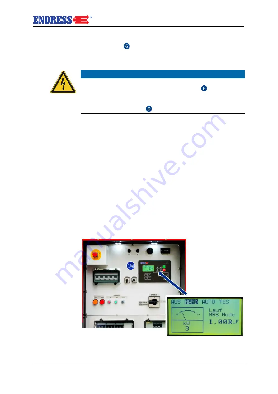
The dummy load is controlled automatically and requires no intervention by op-
erating personnel. You can tell the dummy load is active when the control module
display shows power output when no or only minor consumers are turned on (in
the example below, 3 kW).
Fig. 9-2 Display with dummy load operating


