background image

www.enelx.com

 Phone: +1-844-584-2329

Important safety instructions and specifications.  Save these instructions.........................1

FCC Notice.............................................................................................................................3

Packaging, handling & receipt...............................................................................................4

Site configuration...................................................................................................................5

Underground power preparation...........................................................................................9

Above ground power preparation........................................................................................10

Installation requirements & equipment...............................................................................11

Unpacking & installation preparation...................................................................................13

Installation............................................................................................................................16

Underground conduit and wiring..........................................................................................18

Above ground conduit and wiring........................................................................................20

Wire & commission...............................................................................................................21

Ethernet port access............................................................................................................23

Closing checklist...................................................................................................................24

Installation checklist.............................................................................................................27

Contents

Summary of Contents for JuicePump

Page 1: ...50kW DC RT www enelx com Phone 1 844 584 2329 Installation Manual TRI93 50 01 UL ...

Page 2: ......

Page 3: ...t 4 Site configuration 5 Underground power preparation 9 Above ground power preparation 10 Installation requirements equipment 11 Unpacking installation preparation 13 Installation 16 Underground conduit and wiring 18 Above ground conduit and wiring 20 Wire commission 21 Ethernet port access 23 Closingchecklist 24 Installationchecklist 27 Contents ...

Page 4: ...re the char ger is re energized Grounding instructions This unit is to be connected to a grounded metal permanent wiring system and an equipment grounding conductor is to be run with circuit conductors and connected to equipment grounding terminal or lead on battery charger Connections to the bat tery charger shall comply with all local codes and ordinances Observe all pertinent national regional ...

Page 5: ...anch circuit over current protection in accordance with the National Electrical Code ANSI NFPA 70 Tightening torque Wiring terminals Breaker 4 0 Nm 35 lb in Service hatch 2 0 Nm 17 70 lb in Operating temperature 35 to 50 C 31 to 122 F Maximum ambient temperature 55 C 131 F Weather rating NEMA Type 3R Important safety instructions and specifications Save these instructions ...

Page 6: ... in accordance with the instruction manual may cause harmful interference to radio communi cations Operation of this equipment in a residential area is likely to cause harmful interference in which case the user will be required to correct the interference at his own expense Modification warning FCC Part 15 21 In addition the user s manual or instruction manual shall caution the user that changes ...

Page 7: ...the original packaging in a horizontal position Storage temperature 20 to 45 C 4 to 113 F Handling Only lift the JuicePump packaging in its horizontal orientation using a forklift pallet jack or with lifting straps and engine hoist forklift or crane Check the weight on the delivery documents and ensure the lifting apparatus used is compatible Receipt Check that the crate packaging is in good condi...

Page 8: ...5 8 11 inch fasteners not supplied The fasteners should fix the Veefil securely to the foundation through the baseplate and protrude 30 40mm 1 2 1 6 inch maximum from the foundation surface in accordance with the dimensions and fixing points shown in Figure 5 Fixing guide See Figure 1 Dimensions walls or obstacles for installation against or near walls or other obstacles Foundation requirements Th...

Page 9: ...easurement requirements Contact your Enel X representative for installation advice if your mimimum measurements are smaller than shown in Figure 1 28 5 725 minimum 6 3 160 9 8 250 11 8 300 Do not scale Wall Wall Figure 1 Dimensions walls or obstacles 28 5 725 minimum ...

Page 10: ... to the JuicePump sides at all times Single carparking bay To service one car bay 500mm 20 inches of space is recommended between the car and the JuicePump front and back for ease of use Wheel stops installed at 1200mm 4 feet from the centre front of the JuicePump can achieve this If the JuicePump is to be installed with it s back or sides against or near a wall or other obstacle use the minimum d...

Page 11: ...observed use the dimensions for foundation positioning in Figure 3 30 3 72 2 7 68 6 3 160 16 410 11 8 300 Figure 3 Back to back units Do not scale 6 3 160 30 3 72 2 7 68 Site configuration servicing A additional space of 700mm 27 5 inches from the center front of the baseplate is required to open the front panel for servicing as shown in Figure 4 Do not scale 27 5 700 Figure 4 Servicing distance r...

Page 12: ...e 50mm power hole location in relation to the mounting studs This ensures the sealing of the supplied flexa conduit system into the foundation Fixing points Use 4x 5 8 11 studs protruding 1 2 1 6 inches above the surface If the studs protrude more than this it will be impossible to remove and replace the radiator if required Ethernet cable hole If hardwiring in the ethernet use this hole for the c...

Page 13: ... JuicePump via the back radiator panel on the left hand side as shown in Figure 6 Use the JuicePump template supplied in the crate kit or or measure as per Figure 5 to ensure the fixing points are correct Locate mounting studs and conduit within 0 05 1 25mm tolerance To ensure the correct seal is maintained into the JuicePump only use Flexa 1 1 4 inch ROHRflex conduit order code 0237 202 036 not s...

Page 14: ...mp must be properly in stalled assembled and commissioned according to these instructions before it is used Prior to installation contact your supplier to organise commissioning information Supplied with JuicePump 5mm pin hex tool to remove the M8 security screws fixing the plastic panels 2 5mm hex L wrench Lifting straps Blanking plugs are fitted for transport and storage Flexa conduit system Bla...

Page 15: ...6 or 5 8 11 galvanised nuts to match fasteners Flexa PN 0237 202 036 conduit above ground power installations only Tools Socket set ratchet or adjustable spanner Allen keys or socket set hex bits Power driver Sockets required 8mm for radiator removal and service hatch removal 10mm socket for earthing strap removal 16mm for removal of shipping baseplate bolts Approved external sealant DOCUMENT KEY ...

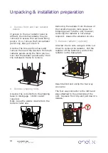
Page 16: ...attach the lifting straps at the top of the JuicePump to the lifting appa ratus and gently raise to a standing posi tion on the shipping baseplate The JuicePump must remain attached to the lifting equipment until the mounting bolts have been installed NOTE The JuicePump is 2050mm 6 72ft tall on the shipping baseplate Do not use the plug holders to assist lifting the charger at any stage Once uprig...

Page 17: ... attached to the underside of the unit Squeeze front clip and pull down to release 3 Remove front and rear radiator panels If access to the rear radiator panel is difficult the internal radiator may be removed to access the rear base fixing points If so remove the front radiator panel only and go to item 5 Unscrew the 8x security screws and remove them and the washers from both radiator panels usi...

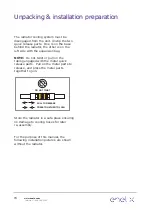
Page 18: ...not twist or pull on the tubing engaged with the metal quick release parts Pull on the metal parts to release and press the metal parts together to join PULL DO NOT TWIST PULL TO RELEASE PRESS TOGETHER TO JOIN Store the radiator in a safe place ensuring no damage to cooling hoses for later re assembly For the purpose of this manual the following installation pictures are shown without the radiator...

Page 19: ...t panel connected during commissioning If this is possible go to page 17 item 5 If in doubt disconnect the front panel see pg 17 item 4 and store in a safe place until the unit is ready to close for use 1 Secure to foundation Lift the JuicePump by the supplied lifting straps place onto the prepared foundation and secure with the specified fasteners Note Use the plastic inserts you kept earlier in ...

Page 20: ...upply power If pre installation power up is required contact your supplier to synchronize with Enel X 7 Remove IEC cable wiring Remove the M40 blanking plug and IEC cable wiring from the switch gear 4 Disconnect front panel There are three points to disconnect 1 Wiring to the top rear panel Squeeze the connector to disconnect 2 Earthing strap Unscrew the nut on the metalwork with a 10mm socket Rem...

Page 21: ...g Pull out conduit 2 Fit Flexa system into base Install the 6 conduit nipple conduit coupling and flex adapter into the embedded 6 coupling not supplied in the foundation using sealant on all threads Underground conduit and wiring The JuicePump is supplied with a Flexa conduit system in the crate kit with all parts attached 6 conduit nipple conduit coupling flex adapter flexa conduit flex adapter ...

Page 22: ...with the locking ring 4 Feed through wiring Pull the wires from the service disconnect into the switchgear area running at least 12 300mm of wiring into the interior Connect the wires to the terminal block according to the wiring diagram inside the service hatch Also see section Wire and Commission in this document To achieve the NEMA 3R rating the conduit must be fitted correctly into the supplie...

Page 23: ...s fit into the flex adapter Use the slots in the rear channel to cable tie the conduit in place if necessary 415V 3PH Copper Conductors Only N x 4 Feed through wiring Pull the wires from the service disconnect into the switchgear area running at least 12 300mm of wiring into the interior Connect the wires to the terminal block according to the wiring diagram inside the service hatch Also see secti...

Page 24: ...f the switch gear so they will not interfere with the service cover When completed switch on the breaker and check the interface panel on the front door is cycling through the icons Each icon will be lit in turn on the interface panel Contact your supplier to run through the diagnostic testing to commission the unit CAUTION When the wiring and cabling is connect ed refit the service cover BEFORE y...

Page 25: ...over Tightening Torque Breaker 4 0 Nm 35 lb in Check the breaker terminals are tightened to the above settings Trim the wires leaving a minimum of 300mm 12 inches exposed Single phase wires thread through the small black ferrite 1 only Three phase brown orange yellow and green yellow ground wiring thread firstly through the large grey ferrite 2 Three phase brown orange yellow only thread through t...

Page 26: ...ated under the enclosure box on the back left The rear radiator panel must be removed to access this location Twist to disengage the cap and plug in the ethernet cable If hardwiring in the ethernet cable please see page 5 for connector details Ethernet port access ...

Page 27: ...sh remove and ensure the wiring is sitting behind the lower face of the switch gear 3 Attach service hatch over service cover Check the gasket has not been damaged or soiled If using a power drill to fasten the nuts ensure the correct torque setting of no greater than 2 0 Nm 17 70 lb in If using hand tool fasten until resistance felt Do not over tighten 4 Re attach radiator if required Angle the r...

Page 28: ...nd security screws using the 5mm Pin Hex tool Do not over tighten If the power is above ground the rear radiator panel provides the exit point for the conduit from the JuicePump Cut the four tabs on the lower right hand of the radiator panel to remove the material to open the conduit exit point TAB 1 TAB 3 TAB 4 TAB 2 Replace the rear radiator panel ensuring the conduit is fitted securely within t...

Page 29: ...Attach front panel Gently place the front panel on the top hook ensuring the panel sits outside the fastening brackets Sit on the radiator panel and check the top hook is engaged It will hold in position Secure with the nylon washers and security screws with the 5mm Pin Hex tool ensuring the plastic holes line up with the bracket nutserts Do not over tighten 9 Complete installation checklist Compl...

Reviews: