ML0071-601-06 Super Seal™ Operations Manual Rev. A
ENERCON INDUSTRIES
12
Deep Tunnel Sealing Head
The Deep Tunnel Head is typically used on special
applications where the cap or container will not allow
the product to fit within the standard tunnel head.
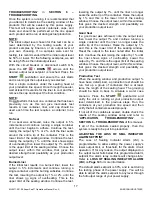
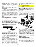
Deep tunnel head have a centerline indicator at the
top of the tunnel and foil indicators on both sides of
the tunnel. In these applications, the center
alignment should be set with the cap in place but the
sealing head height should be set with the cap
removed. Align the foil indicators to the lip of the
container where the foil liner rests. If cap or container
dimensions prevent the lip of the container from
reaching the centering marks then position the
container lip into the tunnel as far as possible
(Figure 22)
.
CENTER LINE
FO
IL
FO
IL
LINER &
CONTAINER LIP
Cap & Liner must be
aligned with all 3
labels.
Figure 22
Alignment And Adjustment “1” Sealing Head
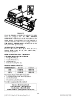
In many instances, multiple cap sizes will be run on
the same power supply. The “1” Sealing Head and
Pivot Kit allows for moving the sealing head to
accommodate various size caps without having to
exchange the sealing head. The “1” sealing head
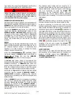
can be pivoted in approximately seven (7) degree
increments to four different positions
(Figure 23)
.
100 - 120
63 - 89
20 - 38
43 - 58
CAP
(mm)
CAP
(mm)
63 - 89
100 - 120
43 - 58
20 - 38
4
4
3
2
1
3
2
1
Figure 23
The table that follows indicates the desired pivot
position
for the listed liner sizes. The pivot assembly
brackets serve to guide the sealing head rotation,
providing the proper pivot angle for the liner sizes you
are sealing. The knurled locking knobs serve to lock the
sealing head in place.
NOTE:
No tools are required to change the position of the
sealing head. Loosen both of the knurled locking knobs,
one at each end of the sealing head. Rotate the sealing
head to the proper position for the cap size in use.
Center the proper indicator line on the locking knobs at
each end of the sealing head and hand tighten the
locking knobs.
Item #
Description
1
20 – 38mm Position
2
43 – 58mm Position
3
63 – 89mm Position
4
100 – 120mm Position
Proper alignment of the “1” Sealing Head is critical, use
the following steps for proper set up.
1. First align the power supply and sealing head over
the conveyor with the sealing head in the #1
position. The mount / cart must be secure.
2. Align and gap the product to the sealing head using
the same criteria used for a Flat Sealing Head
(See
Figure 20)
ensuring that it runs centered along the
entire length of the sealing head.
3.
Choose the proper position for the caps size to be
run and pivot the sealing head to that position,
Refer
to table above.
NOTE:
Check alignment whenever the pivot angle is to be
changed to ensure proper sealing.
SYSTEM REQUIREMENTS
Temperature
The Super Seal™ has been designed to operate in
an ambient air temperature range of 32º-104º F (0º-
40º C) @ 80% relative humidity, non-condensing.
Input Voltage Requirements
The
Super Seal™
requires a specific input voltage to
function properly. The required input voltage is listed
on the rating plate on the side of the power supply
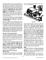
(See Figure 4 on Page 6)
, and in the drawing list
provided with your system. The standard voltages
required are 208 or 240 VAC ± 10%, 1Ø / 3Ø, 50/60
hertz.
WARNING!
The power supply should not be operated
without the grounded line cord connected to a
grounded receptacle.
DO NOT bypass the ground terminal.
Grounding Requirements
All system components must be connected to a good
earthen ground point using the green ground wire


