ML0071-601-06 Super Seal™ Operations Manual Rev. A
ENERCON INDUSTRIES
13
provided in the power cord. Local codes will dictate
the means of terminating the ground wire. A fused
disconnect switch must be located between the input
voltage source and the power supply.
BASIC SYSTEM
Each
Super Seal™
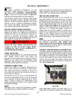
is supplied with 2 standard cables
and 2 defeat connectors. The two cables provided are
the Remote Start / Interlocks Cable (
1
) and the Alarm
Connector Cable (
2
). The 2 defeat connectors are for
the
REMOTE START / INTERLOCKS
circuit (
1
) and
STALLED BOTTLE SENSOR
circuit (
3
). Both the
cables and defeat connectors will connect to the rear
panel of the power supply
(Figure 24)
.
INTERLOCK DEFEAT CONNECTOR
(USED WHEN NEITHER INTERLOCKS NOR
REMOTE START ARE REQUIRED)
TO CUSTOMER
N.O. INTERLOCK
CONTACT
TO CUSTOMER
N.O. REMOTE
START CONTACT
BLACK
RED
WHITE
GREEN
BLACK
RED
WHITE
FOR CUSTOMER LOSS OF
SEALING INDICATOR (LSI) ALARM,
USE AS REQUIRED
1
2
REMOTE START /
INTERLOCKS
AUTO
CONTROL
STALLED
BOTTLE SENSOR
FOIL DETECT
SENSOR ASSY
STACK
LIGHT
LSI
CONTACTS
FOIL DETECT
CONTACTS
1
2
3
3
STALLED BOTTLE DEFEAT CONNECTOR
(REQUIRED WHEN NEITHER OF THE THE MOTION
OPTIONS ARE INCLUDED WITH YOUR SYSTEM)
Figure 24
BASIC INTERCONNECTIONS
Using The Remote Start / Interlocks Cable
A cable is provided to extend the wiring of the
Remote Start / Interlock cable to external contacts as
shown in
Figure 24
. Connect the Remote Start /
Interlock cable securely to the rear panel of the
power supply and run the open end of the cable to
your N.O. dry contacts. Ensure you use the Black
and Red wires for the Interlock function and the
White and Green wires for the Remote Start function.
The Remote Start function is tied to the
LOCAL/REMOTE
pushbutton located on the front
panel of the unit.
External Interlock
The
Super Seal™
comes standard with provisions
for interlocking the control circuits. The two interlock
wires must be connected to a normally open contact
that closes when the interlock is met for the unit to
start. This “closed circuit” may be accomplished in a
number of different ways but is absolutely necessary
for the unit to start and run. Do
not
apply any voltage
across these wires.
WARNING!
Applying voltage to the interlock control
circuits may result in a failure of circuit
components.
DO NOT APPLY VOLTAGE ACROSS THE
INTERLOCKS!
Remote Start
The
Super Seal™
comes standard with provisions
for starting and stopping the power supply remotely.
The two remote start wires must be connected to a
normally open contact and the contact must be
closed to start the power supply and open to stop it
(Refer to
REMOTE START OPERATION
on
Page
19
).
Do
not
apply any voltage across these wires.
USING THE DEFEAT CONNECTORS
Remote Start / Interlocks
A defeat connector is included to provide the
required closed circuit for the interlocks when the
interlock and remote start functions are not used.
This simply requires connecting the defeat connector
to the
REMOTE START / INTERLOCKS
connector
on the rear panel of the power supply. The jumper
wire inside the defeat connector allows the unit to
start without providing an external closed contact.
Stalled Bottle Sensor
A second defeat connector is included to provide the
required closed circuit for the Stalled Bottle Sensor
circuit when none of the Motion options is included
with your system. This simply requires connecting
the defeat connector to the
STALLED BOTTLE
SENSOR
connector on the rear panel of the power
supply. The jumper wire inside the defeat connector
allows the unit to start without having the optional
stalled bottle sensor connected to the power supply.
Refer to
SECTION 4 – OPTIONS
for further details
on the Motion Options that are available.
NOTE:
Even if you are not using either of the defeat
connectors, ensure you
do
not
discard either of
them. Keep them in a safe place, as they may be
required to substitute for the
Remote Start /
Interlocks
cable or the
Stalled Bottle Sensor
,
if
they are damaged, or for troubleshooting these
circuits.


