ML0071-601-06 Super Seal™ Operations Manual Rev. A
ENERCON INDUSTRIES
25
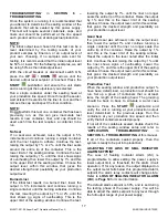
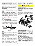
b)
Remove the sensitivity adjustment pot cover
screw
(Figure 37)
.
c) With a container (and foil-lined cap) under the
proximity sensor, verify that the LED is ON. If LED
is OFF go to Step (
e
).
d) Turn the sensitivity adjustment CW (clockwise)
until the LED just turns OFF. In some cases, the
LED will not turn OFF
.
If not
,
proceed to
Step (
f
).
e) Turn the sensitivity CCW (counter clockwise) until
the LED just turns ON.
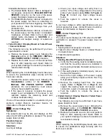
LED
Cover
Screw
Sensitivity
Adjust
Figure 37
f) Remove the container and the LED should turn
off.
g)
Turn the potentiometer CCW (counting the
number of turns) until the LED just turns ON.
h) Back off half the number of turns counted in Step
(
g
).
i) The LED should now be OFF. Sensitivity should
now be set at optimum.
AUTO MODE
The AUTO Mode Option is offered with the Super
Seal™ power supply as a way to automatically
control the power supply output from an external
source. This option allows the raising and lowering of
the Output level using an isolated 0–10 VDC signal
that you provide. The unit also provides a 0-10 VDC
output signal for monitoring of the output level. A
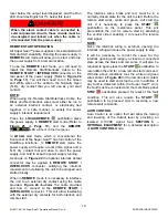
three wire cable is provided to connect to the
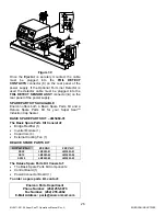
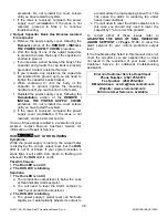
AUTO
CONTROL
connector on the rear panel of the power
supply
(Figure 38)
.
The cable wiring is
white
/ 0-10
VDC input signal,
red
/ 0-10 VDC output signal,
black
/ common and a
shield
.
To enter
AUTO MODE
the
AUTO/MANUAL
pushbutton on the front of the power supply must be
pressed. The
AUTO
LED should be lit. It is required
to press the
START
pushbutton on the
membrane panel to start the unit.
REMOTE START /
INTERLOCKS
AUTO
CONTROL
STALLED
BOTTLE SENSOR
FOIL DETECT
SENSOR ASSY
STAC
LIGHT
FOIL DETECT
CONTACTS
LSI
CONTACTS
BLACK (COM)
SHIELD
WHITE (0-10VDC IN)
RED (0-10VDC OUT)
Figure 38
Raising and lowering the 0-10 VDC being fed to the
unit will raise and lower the output of the power
supply. Maintain the minimum output level as
discussed under
ADJUSTING THE LOSS OF SEAL
INDICATOR ALARM SETPOINT
on
Pages 17
-
18
,
for the model power supply being used.
NOTE:
Slightly less than 10 VDC may achieve 100%
Output, limit voltage to achieve 100% maximum on
Output Meter.
DANGER!
When the AUTO Mode Cable is connected to
external circuits, these circuits must be de-
energized and locked out when the cable is
disconnected at the power supply.
JECTOR SYSTEM
The Enercon Eject System was designed to provide
a simple ejection system to remove rejected
containers off your conveyer. The Eject System can
be used with the Motion/Foil Detection Group, Foil
Liner Detector only, or other container inspection
systems that provide a dry contact closure when a
reject is detected. The system accepts the contact
closure and once timed out, the Eject System is
activated, causing the plunger to eject the container
off the conveyor. Refer to Ejector Manual
(ML0068-
001-XX)
and Drawings supplied with the Eject
System for more detailed information.
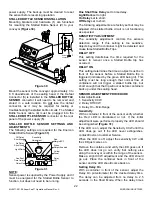
JECTOR INSTALLATION
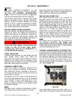
Mounting brackets and hardware are (
1
) furnished
for mounting the Ejector (
2
) to your conveyor
(See
Figure 39)
. The Ejector is designed to work with the
Optional Enercon Foil Liner Detector and should be
mounted downstream of the detector in a location
that will allow the ejected containers to be collected.


