ML0071-601-06 Super Seal™ Operations Manual Rev. A
ENERCON INDUSTRIES
34
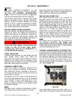
c. Reinstall the power supply cover, following the
Reinstallation
portion of the
REMOVE /
INSTALL THE POWER SUPPLY COVER
procedure. Do not reinstall the cover screws
until you have tested the system.
d. If the issue is resolved, complete the power
supply cover reinstallation. If the issue is not
resolved, replace the remaining board and
continue troubleshooting.
If none of these steps resulted in a resolution of your
problem, contact Enercon Customer Service for
information on Repair or Service.
3.
Failed output Capacitors
Under certain circumstances, a medium frequency
Super Seal™ power supply will display the F05
indication when an output capacitor(s) has failed
while running. Typically, the F05 will continue to
be displayed upon attempting to restart the power
supply.
a. If the previous steps for this issue have not
resolved this problem, perform the capacitor
issue troubleshooting called out under
F02
AND TEMP – CAP TRIP OR OVER-TEMP
troubleshooting.
If none of these steps resulted in a resolution of your
problem, contact Enercon Customer Service for
information on Repair or Service.
THE FRONT PANEL IS BLANK
Symptoms:
The Output Meter and Indicator LEDs are not lit
when the input voltage is applied to the power
supply.
NOTE:
Depending on the cause of this issue, the cooling
fans may, or may not, be turning. If the cooling fans
are not
turning, this symptom will be associated with
causes 1, 2 & 3. When the cooling fans
are
turning,
this symptom will be associated with causes 4 & 5.
Possible Causes:
1. Power Supply is disconnected from the input
voltage.
2. The input voltage is being interrupted.
3. Failed power supply circuit breaker or disconnect
switch.
4. Ribbon Cable / Wiring issue.
5. Failed Control / Display board, or a failed Power /
Connector board.
Solutions:
The cooling fans
are not
turning.
1.
Power Supply Is Disconnected From The Input
Voltage
a. Ensure that the power supply is plugged in, or
properly connected to the fused disconnect.
b. Test to see if the front panel lights up.
2.
The Input Voltage Is Interrupted
a. Ensure any disconnect boxes are on and that
any fuses are good. Turn disconnect boxes on
or replaced failed fuses.
b. Check the main electrical panel and ensure the
supply breaker is not tripped, or that its fuses
are good. Turn the supply breaker on or
replaced failed fuses.
3.
Failed Power Supply Circuit Breaker or
Disconnect Switch
a. Remove the power supply cover, following the
Removal
portion of the
REMOVE / INSTALL
THE POWER SUPPLY COVER
procedure.
b. Check the condition of the circuit breaker or
disconnect switch, if damaged replace as
required.
c. With the circuit breaker or disconnect switch in
the ON position, ohm out the breaker or switch
and replace if an open is read across any of the
poles.
e. Reinstall the power supply cover, following the
Reinstallation
portion of the
REMOVE /
INSTALL THE POWER SUPPLY COVER
procedure. Do not reinstall the cover screws
until you have tested the system.
d. If the issue is resolved, complete the power
supply cover reinstallation. If the issue is not
resolved, continue troubleshooting.
The Cooling fans
are
turning.
1.
Ribbon Cable / Wiring Issue
a.
Partially remove the power supply cover,
following the
Removal
portion of the
REMOVE
/ INSTALL THE POWER SUPPLY COVER
procedure, but do not remove the ribbon cable
and wires 1 & 2.
b. Inspect the ribbon cable and wires 1 & 2 at
both boards. Reconnect, or replace as
required.
c. Reinstall the power supply cover, following the
Reinstallation
portion of the
REMOVE /
INSTALL THE POWER SUPPLY COVER
procedure. Do not reinstall the cover screws
until you have tested the system.
d. If the issue is resolved, complete the power
supply cover reinstallation. If the issue is not
resolved, continue troubleshooting.
2.
Failed Control / Display Board or Failed Power
/ Connector Board
The following can only be performed if you have
spare boards on hand.


