ENERGETICA ENERGIETECHNIK GMBH
Adi-Dassler-Gasse 6 | A-9073 Klagenfurt-Viktring
Tel. +43 (0) 463 22500-0 | Fax. +43 (0)463 22500-22 | Email: office@energetica-pv.com
A
A
A
ATTENTION
TTENTION
TTENTION
TTENTION!!!!
•
Only fasten and install the modules with the mounting
system that is provided or with a suitable corrosion-
resistant mounting system.
•
During the installation of the modules, make sure that there
is enough air circulation to cool the modules.
•
Only mount the module upright with the junction box up, or
mount it crosswise.
•
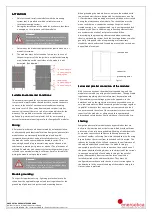
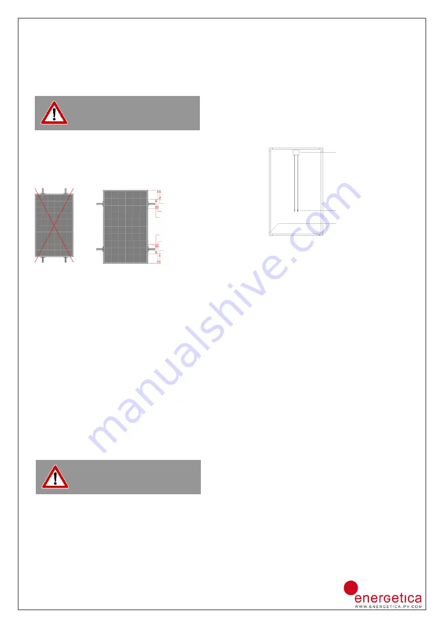
The modules must be fastened on four points, in each of
the quarter points of the long side in a stipulated clamping
area. Fastening on the short sides of the module is not
permitted. (See drawing)
Suitable Environmental Conditions:
Suitable Environmental Conditions:
Suitable Environmental Conditions:
Suitable Environmental Conditions:
The module is designed for use in moderate climatic conditions.
It must not be immersed nor be subjected to constant exposure
to water. In the event of environmental conditions involving
exposure to salt (500 m away from sea) and sulphur (sulphur
sources, volcanoes), there is a risk of corrosion which voids the
warranty. The module must not be subjected to chemical
pollution (e.g. emissions from plants). Ask for our mounting
system for optimum mounting results for Energetica PV modules.
Wiring:
Wiring:
Wiring:
Wiring:
All electrical work may only be performed by trained specialists
or alternatively an authorised electrician. Energetica photovoltaic
modules have a permanently installed junction box with
integrated bypass diodes and preinstalled connectors. That way,
the modules can be conveniently connected in series. The
connecting box and plug connectors may not be cleaned with
substances containing oil, grease, or alcohol. The placement of
multiple PV modules on a support system with common wiring is
referred to as a module string. Ask for our 6mm
2
solar cable for
wiring the module string to the inverter.
Modul
Modul
Modul
Module grounding:
e grounding:
e grounding:
e grounding:
The specific requirements (e.g. lightning protection) are to be
taken from the applicable regional and local regulations for the
grounding of photovoltaic systems and mounting frames.
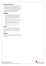
When grounding the module frames, only use the marked earth
connection points that are designated for that purpose (see Fig.
1). Furthermore, the grounding must not be broken or destroyed
during the maintenance of a module. The connection must be
made such that non-conductive coatings like paint, anodic
treated coatings, etc., are penetrated (e.g. by using toothed lock
washers or the like). In addition, any connecting elements that
are used must be made of rustproof materials. When
dimensioning the grounding elements and when connecting
them to a grounding system, both the local regulations as well as
generally recognised rules of engineering or alternatively
standards must be observed. Grounding may only be carried out
by qualified electricians.
Figure 1
Series and parallel connection of the modules:
Series and parallel connection of the modules:
Series and parallel connection of the modules:
Series and parallel connection of the modules:
With series connections, the module voltage adds up, and the
module current adds up with parallel connections. The applicable
regulations regarding electrical safety must be complied with.
The maximum system voltage given in the appendix, in the
datasheet, and on the type plate must not be exceeded, even at
very low temperatures. When connecting module strings together
in parallel, make sure that any return current caused by a fault
can never exceed the value of the maximum return current load
capacity of the modules, or alternatively that appropriately
dimensioned safety devices like line diodes or fuses are built in.
Shading:
Shading:
Shading:
Shading:
Energetica photovoltaic modules have bypass diodes that are
built into the junction box at the factory, which provide efficient
protection of the cells during shading. Shading of individual cells
or modules causes the shaded area to heat up because the
current of another cell string flows into the shaded area. By using
bypass diodes, the current from the shaded cell is diverted. This
reduces the heating of the cell and increases the performance of
the module under shady conditions. If a module string is
connected in parallel to a series connection, then switch one of
the power adapted blocking diodes in the direction of the current
in one connecting lead of each module string of the parallel
group. Alternatively, direct current line fuses can also be
installed instead of the additional diodes. They must be
configured in accordance with the short-circuit current given in
the datasheet. In the event of shading of the module string, the
first variation is preferred.
Attention!
Attention!
Attention!
Attention!
When installing the module, always make sure
that there is sufficient back ventilation to
ensure optimum heat dissipation.
Attention!
Attention!
Attention!
Attention!
The connection box must not be subjected to
high strain / pressure. If it is destroyed, there
is a danger of an electric shock.
1/8 module length
1/4 module length
clamping area
clamping area
1/4 module length
1/8 module length
Junction box
connector
grounding point


