background image

Electrical installation

General Wiring

»

  Energetica Industries GmbH recommends double 

      insulation of all cabling with a temperature resistance of 
      at least 90 ° C (194 ° F).

» 

All wiring should be made of flexible copper conductors 

      (Cu).

» 

The minimum size must be determined in accordance 

      with the applicable regulations.

» 

Energetica Industries GmbH recommends a minimum 

      size of 6 mm.

Grounding

» 

All work must be carried out in accordance with applica-

      ble national, regional and local regulations and stan- 
      dards.

» 

For safety reasons and to maintain the system, the solar 

      modules must be grounded by an authorized installer in 
      accordance with applicable national, regional and local 
      regulations and standards for electrical installations.

» 

Specific information on the dimensions of the solar 

      modules and the positioning of the grounding holes can 
      be found in the product specifications on page 13.

» 

One M4 stainless steel screw, one nut, one spring washer, 

      two flat washers, one cup washer, one tooth lock washer 
      and 12 AWG copper wire are recommended for each 
      installation hole.

» 

If customary earthing accessories (nuts, screws, washers)

      are used to install a listed earthing device, the installation
      must be carried out in accordance with the relevant
      manufacturer's instructions.

» 

All parts used should be made of corrosion-resistant 

      material such as stainless steel.

» 

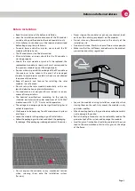
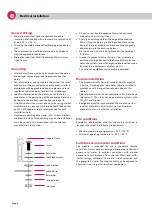
There is an earthing hole on the edge of the module 

      frame. Using this hole, a grounding conductor and the 
      frame of the solar module can be connected and groun
      ded according to the drawing below.

» 

All screws and nuts must be tightened with a torque of 

      4 ~ 5 Nm.

» 

In order to prevent electric shocks or fires, protective 

      earthing must be attached to the frame of the solar mo
      dules and systems, even if Energetica photovoltaic modu
      les meet the requirements of safety class II. 
  The national regulations must always be observed.

Module installation

» 

The limited warranty for solar modules from Energetica 

      Industries GmbH applies to modules that are installed in 
      accordance with the specifications described in this 
      section.

» 

The solar modules fall under application class A and have 

      safety class II. Thus, they can be operated in systems with 
      120 V DC and higher. 

» 

Energetica Industries recommends the use of corrosion- 

      resistant materials such as screws, nuts and washers 
      made of stainless steel for the installation.

Site conditions

Energetica photovoltaic modules should be installed in 
locations that meet the following requirements:

» 

Maximum operating temperature: +90 °C (194 °F)

» 

Minimum operating temperature: -40 °C (-40 °F)

Suitable environmental conditions

The module is intended for use in moderate climatic 

conditions. It must not be submerged or exposed to constant 
exposure to water. In ambient conditions with greater 
exposure to salt (distance from the sea 500m) and sulfur 
(sulfur springs, volcanoes) there is a risk of corrosion and 
the guarantee is void. The module must not be exposed to 
chemical strains (e.g. emissions from companies). 

module frame

screw

flat washer
tooth lock washer

plate washer

ground wire
flat washer

spring washer

screw nut

Page 8

e

Summary of Contents for e.CLASSIC M HC

Page 1: ...INSTALLATION MANUAL e CLASSIC M HC e CLASSIC M HC black www energetica pv com V1 o 26 11 2020...

Page 2: ...tion 4 Electrical connections 5 e ISP Energetica Integrated Shadow Protection 5 Series connection 6 Series connection parallel connection 7 General wiring 8 Grounding 8 Module installation 8 Site cond...

Page 3: ...of the photovoltaic modules e Classic M HC e Classic M HC black from Energetica Industries GmbH hereinafter referred to as the PV module Read this manual carefully before starting the installation All...

Page 4: ...GmbH assumes no liability for damage resulting from failure to observe these instructions It is the responsibility of the system installer to observe the wiring and dimensioning of the system as well...

Page 5: ...ding to the industry standard are determined under conditions of 1 000 W m2 Irradiance and 25 C 77 F solar cell temperature The voltage and amperage can be significantly higher at colder temperatures...

Page 6: ...he module when connecting If the return currents exceed the maximum value specified on the type label or in the data sheet a correctly di mensioned and certified overcurrent device fuse or circuit bre...

Page 7: ...represents a much more effective protection of the module in the event of unforeseen shading and thus optimizes the power loss of the modules in the event of shading IMPORTANT SAFETY INFORMATION Corre...

Page 8: ...s or insulation faults but also personal injury and property damage IMPORTANT SAFETY INFORMATION If the module strings are connected in parallel external diodes blocking diodes adapted to the output a...

Page 9: ...ve the desired amperage If the modules are connected in parallel the total ampe rage is the sum of the amperages of the individual mo dules The voltage of all modules connected in parallel should be i...

Page 10: ...the frame of the solar module can be connected and groun ded according to the drawing below All screws and nuts must be tightened with a torque of 4 5 Nm In order to prevent electric shocks or fires p...

Page 11: ...anufacturer s instructions After installation there must be no electrical parts such as cables between the laminate and the substructure Make sure that the plug connections are never in the water Deta...

Page 12: ...ve parts on your body or clothing In order not to damage the module surface clean the modules as follows Remove snow and ice carefully and without effort For example use a soft broom for this Do not s...

Page 13: ...10 mm 210 mm MV3 Point bearing without rail 1 5 210 mm 210 mm 210 mm MV4 Please note the specification of the permissible static load and the clamping range on the following page The installation vari...

Page 14: ...he clamps or plug in profiles do not touch the glass even under load Make sure that the junction box connection cables do not run between the laminate and the rack rails Make sure that the supporting...

Page 15: ...reverse current load 16 A 16 A Acceptable temperature range 40 C bis 90 C 40 C bis 90 C Protection class junction box IP 68 IP 68 Protection class connector Multicontact MC4 IP68 Multicontact MC4 IP6...

Page 16: ...Notes Page 14 e...

Reviews: