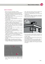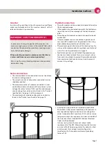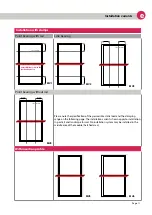
Installation variants
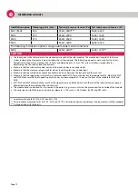
Installation option Clamping point [mm]
Test load pressure/tension [Pa] Test load pressure/tension [Pa]
MV1 / MV2
356
5400 / 4000***
3600 /2670
MV3
210
2400 / 2400
1600 / 1600
MV4
210
2400 / 2400
1600 / 1600
MV5
5400 / 4000
3600 /2670
The following installation option is only possible under certain conditions.
MV6
2400 / 2200**
1600 / 1470**
CAUTION
»
»
»
»
»
»
»
»
The loads given in the table relate to the mechanical strength of the solar modules. The mechanical strength of the frame
system including the clamps must be assessed by the system supplier. The following parameters were used for the listed
Energetica test load values: clamp width = 40 mm and clamp depth = 10 mm. The system installer is responsible for
determining the site-specific load requirements.
Make sure that the substructure does not touch the junction box (even under load).
Make sure that the clamps or plug-in profiles do not touch the glass (even under load).
Make sure that the junction box connection cables do not run between the laminate and the rack rails.
Make sure that the supporting structure has a minimum depth of 15 mm on the back of the module for MV5, MV6, MV4, MV2
and MV3. Make sure that the supporting structure has a minimum depth of 10 mm on the front of the module for MV5 and
MV6.
MV1, MV4 and MV2 with rails: Make sure that the module frame is attached directly to the rail of the substructure (no spacers
allowed between the module and the substructure).
The module bends under load. For this reason, sharp objects (e.g. screws) must not be placed near the backside of the module.
Use corrosion-resistant M8 screws and washers (diameter ≥ 15.8 mm or ≥ 0.62 inches) for FB1 and FB2 racks.
* Loads according to IEC 61215-2: 2016 and UL 1703
** Test procedure according to IEC 61215-2: 2016 and UL 1703. Installation options do not meet the requirements of the standards
*** Only permitted with three rails.
Page 12
e
Installation variants

