background image


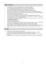
Safety Instructions 


-


To protect the floor or carpet from damage, place a mat under the treadmill. 

-


Turn off the power whilst the treadmill is not in use and remove the safety key. 

-


In case of emergency please place both feet at the same time on the side reins. 

-


To activate an emergency stop, please detach the safety key from the console. 

-


Ensure that an area of 2000 x 1000 mm behind the treadmill is free from any obstacles. 

-


This product is made for home use only and tested up to a maximum body weight of 120 kilograms. 

-


We take no responsibility for personal injury or damage sustained by or through the use of this treadmill. 

-


The noise creation of treadmill is under 70 db. 

-


The unit requires a power supply of 220V – 230V / 50 HZ. 

-


The function of the immobilization method: the purpose of immobilizing the treadmill is to prevent 

unauthorized use. This can be accomplished by removing the Safety Key from the console, unclipping it 

from the cord and putting it in a non-accessible place. 

-


The emergency dismount: Follow the steps listed below if you experience pain, feel faint or need to stop 

your treadmill in an emergency situation: 

1.) Grip handrails for support. 

2.) Step onto the lateral platform. 

3.) Pull the Safety key off the console. 

-


The function of the emergency stop: The Safety Key functions as the emergency stop. In an emergency 

situation, remove the Safety Key from the console and the treadmill will come to a stop. 

-


Noise compliance: This treadmill meets the requirements of the noise pollution standards. 

-


Search for noisy parts: If you should notice unusual noises, like grinding, clacking etc. try to locate it and 

have it repaired by a professional. Make sure the treadmill is not used until after repairs have been 
made. 


1. 

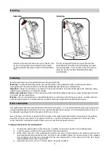
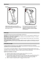
Open the carton, put the main frame on the ground. 

2. 

Fold and move up the computer together with the uprights. IMPORTANT: When you upfoald the 

computer and the uprights, make sure the metal does not damage the inside wires!  

3. 

Fix the uprights to the lower main frame with the bolts and washers as indicated in the set up (drawing) 

manual 

4. 

Fix the computer to the uprights with the bolts and washers as indicated in the set up (drawing) manual 

Assembly 

Summary of Contents for POWER RUN 3.5

Page 1: ...POWER RUN 3 5 GB FR IT RU...

Page 2: ...al specification of the product FR Le manuel d utilisation ne sert que d information au consommateur ENERGETICS ne peut tre tenu responsable pour d ventuelles erreurs de traduction ou pour d ventuelle...

Page 3: ...d inspection of the home exerciser Always start with a warm up session Only use original ENERGETICS parts as delivered see checklist Follow the steps of the assembly instruction carefully Only use sui...

Page 4: ...e emergency dismount Follow the steps listed below if you experience pain feel faint or need to stop your treadmill in an emergency situation 1 Grip handrails for support 2 Step onto the lateral platf...

Page 5: ...admill Vacuum underneath treadmill once a week Deck Lubrication The walking belt has been pre lubricated at the factory However it is recommended that the warking board be checked periodically for lub...

Page 6: ...nto the surge protector and run the treadmill at 4 km h 2 5 mph You should see the belt start to correct itself moving back towards the center Repeat the above procedure until the walking belt is cent...

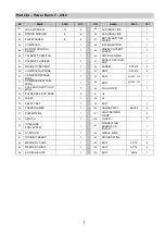
Page 7: ...4 13 INCLINE FRAME 1 43 BOLT M8 35 L25 1 14 SLEEK TUBE ASSEMBLY 1 44 BOLT M8 40 L20 9 15 SLEEK TUBE 1 45 FLAT WASHER 10 2 16 MOTOR TOP COVER 1 46 BOLT M10 55 2 17 BOTTOM BOARD 1 47 BOLT M6 45 1 18 CO...

Page 8: ...ST2 9 8 2 70 COMPUTER MIDDLE WIRE 1 94 BOLT M10 25 L15 1 71 COMPUTER BOTTOM WIRE 1 95 BOLT M10 35 L15 1 72 PULE WITH SWITCH UP WIRE 1 96 PULLING PIN 1 73 PULSE SPEED UP WIRE 2 97 n a 74 LABLE 1 98 n...

Page 9: ...ntenues dans la livraison Voir la liste de contr le Proc dez au montage de l appareil d apr s les instructions de montage N utilisez que des outils appropri s de montage et faites vous le cas ch ant a...

Page 10: ...ente d urgence suivez les indications list es ci dessous si vous ressentez de la douleur un malaise ou si vous avez besoin d arr ter le tapis dans une situation d urgence 1 agrippez vous aux poign es...

Page 11: ...ut passer dessous Passez l aspirateur sous le tapis une fois par semaine Lubrication du tapis Le tapis de marche est pr lubrifi l usine Cependant il est recommand de v rifier sa lubrification r guli r...

Page 12: ...ton gauche de r glage d un quart de tour dans le sens des aiguilles d une montre Rebranchez l appareil et faites rouler le tapis 4 km h Le tapis s ajuste automatiquement et se recentre R p tez cette d...

Page 13: ...5 4 13 CHASSIS INCLINE 1 43 BOULON M8 35 L25 1 14 ASSEMBLAGE TUBE LISSE 1 44 BOULON M8 40 L20 9 15 TUBE LISSE 1 45 RONDELLE PLATE 10 2 16 COUVERCLE MOTEUR 1 46 BOULON M10 55 2 17 PANNEAU DU BAS 1 47 B...

Page 14: ...ABLE ORDINATEUR MILIEU 1 94 BOULON M10 25 L15 1 71 CABLE ORDINATEUR BAS 1 95 BOULON M10 35 L15 1 72 POULS AVEC CABLE INTERRUPTEUR 1 96 CHEVILLE DE TRACTION 1 73 POULS AVEC CABLE VITESSE 2 97 n a 74 CA...

Page 15: ...te sempre esclusivamente le parti originali ENERGETICS contenute nella confezione vedi lista di controllo Durante l assemblaggio dell attrezzo seguite scrupolosamente le istruzioni di montaggio Per il...

Page 16: ...ermare il nastro di corsa all improvviso 1 Appoggiatevi fortemente agli appoggi laterali 2 Salite sulla copertura laterale 3 Tirate fuori dall impugnatura la chiave di sicurezza Funzione d arresto di...

Page 17: ...e che il cavo della corrente sia staccato dalla presa Importante non utilizzate mai detergenti o prodotti lucidanti per pulire il tapis roulant Per proteggere il computer da possibili danni tenetelo...

Page 18: ...o Spruzzate il silicone sulla pedana passando la bomboletta da davanti a dietro fino a circa 6 cm dalla fine del nastro Ripetete l operazione dall altra parte La durata dello spruzzo deve essere di ci...

Page 19: ...in questo caso le istruzioni Il nastro slitta Il nastro spostato a destra tirate dapprima il cavo di collegamento Girate con una chiave adeguata la vite di regolazione destra di un quarto di giro in s...

Page 20: ...IAVE ESAGONA N 5 5mm 1 42 VITE M8 25 L15 4 13 TELAIO PER MODIFICARE PENDENZA 1 43 VITE M8 35 L25 1 14 ACCESSORI DEL TUBO LISCIO 1 44 VITE M8 40 L20 9 15 TUBO LISCIO 1 45 RONDELLA PIATTA 10 2 16 COPERT...

Page 21: ...VITE ST2 9 8 2 70 CAVO MEDIO 1 94 VITE M10 25 L15 1 71 CAVO INFERIORE DEL COMPUTER 1 95 VITE M10 35 L15 1 72 CAVO PER MISURAZIONE DEL POLSO CON L INTERRUTTORE 1 96 PERNO DI ESTRAZIONE 1 73 CAVO PER MI...

Page 22: ...22 EN 957 RU...

Page 23: ...23 2 1 120 70 220 230 50 1 2 3 1 2 3 4...

Page 24: ...24 A 96 14 96 A...

Page 25: ...25 The walking belt has been pre lubricated at the factory However it is recommended that the warking board 500 30 30 1 2 3 6 6 4 4 1 4...

Page 26: ...26 90 4 2 5 90 4 2 5 90 4 2 5...

Page 27: ...5 1 42 M8 25 L15 4 13 1 43 M8 35 L25 1 14 1 44 M8 40 L20 9 15 1 45 10 2 16 1 46 M10 55 2 17 1 47 M6 45 1 18 1 48 M6 55 2 19 1 49 M8 35 5 20 1 50 M8 45 1 21 2 51 M6 35 8 22 2 52 M3 8 2 23 1 53 M5 8 7...

Page 28: ...67 1 91 1 68 1 92 ST2 9 8 2 69 1 93 ST2 9 8 2 70 1 94 M10 25 L15 1 71 1 95 M10 35 L15 1 72 1 96 1 73 2 97 74 1 98 75 1 99 1 76 1 100 600 60 4 77 1 101 2 78 1 102 1 79 1 103 1 80 1 104 1 81 1 105 1 82...

Page 29: ...Woelflistrasse 2 CH 3006 Bern Switzerland Copyright ENERGETICS 2010...

Reviews: