ASSEMBLY AND USER MANUAL
Combi [6 | 12 | 16] & Combi 12 HT
24
www.energie.pt
Upon the initial installation and before establishing any hydraulic connection of the heating circuit to the Combi
Block, the whole hydraulic installation must be cleaned to remove any dirtiness, remains of material and similar
impurities.
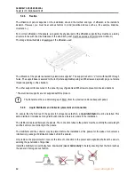
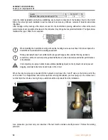
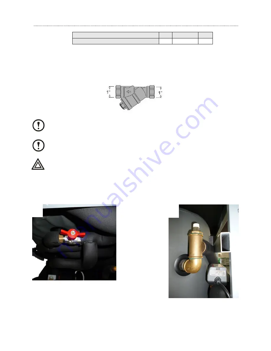
After carrying out the cleaning of the circuit, connect it to the Combi Block, placing, without fail, a filter at the return
water inlet as an accumulation of residues in the condenser may bring about a system malfunction. The figure below
illustrates the type of filter that is supplied.
When installing the Combi Block along with another heating device we must bear in mind and place the
Combi Block in parallel with the existing equipment.
Firstly, preferably choose heat emitters with a large exchange surface (radiant flooring, radiators,
convectors, ventilo-convectors) as they allow distribution at a low temperature and better performances
to be obtained.
It is compulsory to apply an anticorrosive additive (stabilising liquid) on the hydraulic circuit to prevent
clogging, electrolysis phenomena and noise on the circuit.
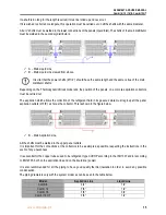
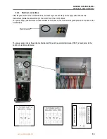
When the circuit is properly connected, fill the hydraulic circuit
(open the “cut
-
off” valve on the botton
part of the
unit, number
1
on image below) and as this operation is being undertaken, you must purge (on the manual vent,
number
2
) all the circuits, ensuring that you eliminate all the air pockets from the installation.
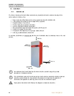
As a precaution, you must carry out a leak test. The test must be carried out with pressure 1.5 times the working
pressure.
Combi
6
12 / 12 HT
16
Minimum flow at the condenser (m
3
/h)
0,7
1,0
1,5
1
2

