background image

ASSEMBLY AND USER MANUAL 

Combi [6 | 12 | 16] & Combi 12 HT 


www.energie.pt


31


9.


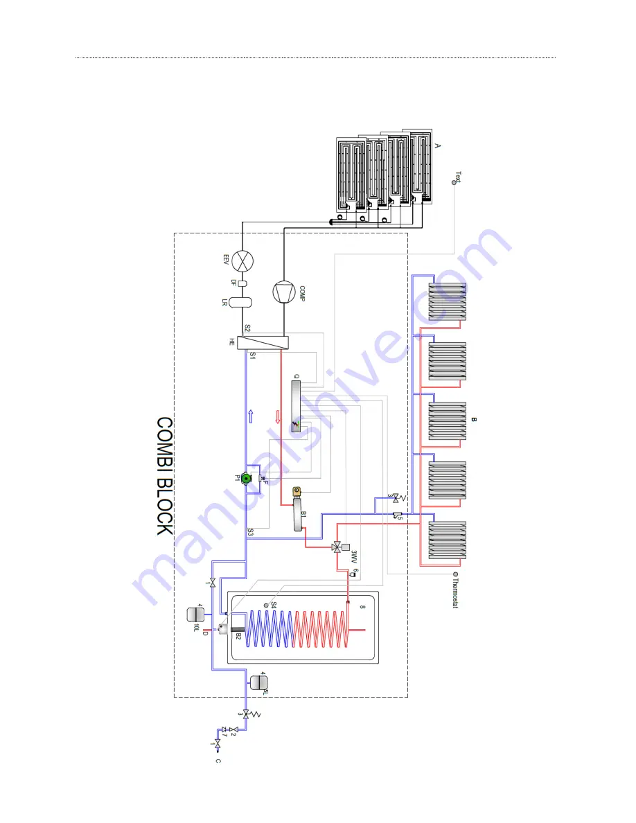
ANNEXES B - INSTALLATION 


9.1.


Plan 


Summary of Contents for Combi 12

Page 1: ...www energie pt 1 Assembly and User Manual Thermodynamic Solar System Combi 6 12 16 Combi 12 HT Directives 2006 95 CE Review 1 Version 0 Date 06 01 2015 CENTRAL HEATING DOMESTIC HOT WATER EN...

Page 2: ...ion 6 4 2 Technical Specifications 7 4 3 Components 8 4 3 1 Combi Block 8 4 3 2 Thermodynamic solar panels 9 5 Installation 9 5 1 Installation Tools required 9 5 2 Thermodynamic Solar Panel 9 5 2 1 Pa...

Page 3: ...st 21 5 3 7 Vacuum 21 5 3 8 Refrigerant R 407C except Combi 12 HT 22 5 3 9 Fluid Charge 22 5 4 Hydraulic Connections 23 5 5 Temperature Probe 25 6 Control Panel 25 7 Error Messages 27 8 Annexes A Wiri...

Page 4: ...tain situations indications In this way we seek to ensure any possible problems for the installer or user and assure smooth equipment performance Warning Important Information Indicates any potentiall...

Page 5: ...ons which must be followed during installation 3 1 Unit inspection The unit was tested and inspected for quality assurance before its dispatch Carefully inspect the equipment components Combi Solar Pa...

Page 6: ...to move the unit without help Transportation and handling must always be done on vertical It is vital to follow all the warnings and recommendations stated on the packaging boxes 3 5 Unit storage If t...

Page 7: ...Weight kg 48 96 128 96 Exposed Capture Surface m 9 6 19 2 26 6 19 2 Refrigerant Type R 407C R 407C R 407C R 134a Amount pre charge kg 1 6 2 2 5 2 Test Pressure bar 30 LP Switch Open Value bar 1 0 3 L...

Page 8: ...heating line It s mandatory to install the safety valve supplied with the system on the heating line Symbol Meaning A Aspiration Line B Liquid Line C DHW Outlet D DHW Inlet E Heating Inlet F Heating...

Page 9: ...high pressure Vacuum Pump Refrigerant gas loading station or scales Pipe cutter Adjustable spanner Screwdriver Measuring tape Tube bender Tube expander Refrigerant gas cylinder Rotoblock wrench Set of...

Page 10: ...t of the solar rays on the panel it s best to choose an inclination between 45 and 90 The panels inclination should never be less then 10 However you may install the panels with another inclination in...

Page 11: ...id at the time of the stoppage of the compressor 5 2 5 Standard Gap of the Panels The position of the panels and the choice of the sides of the connections must be carried out so as to limit the lengt...

Page 12: ...hand panel A Liquid Line Inlet B Vapour Line Outlet Left A left hand panel is installed on the right front view To this end it has connections on the left side The Solar panel must not be installed o...

Page 13: ...lability of the installation area the architectonic integration etc In the diagrams below some of the possible positioning layouts of the panels are represented However you may consult in the annex co...

Page 14: ...way of galvanised M6 screws to prevent corrosion situations The aluminium supports are not supplied with this product The Panels must have a minimum gap of 50cm from the previous and or subsequent pa...

Page 15: ...ied out The aspiration which allows the collection of the refrigerant fluid in its gaseous state must regroup all the panel aspiration outlets 3 8 as far as the collector This is shown in the figure b...

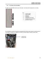
Page 16: ...d Position of the piping from the panels Protected from bad weather such as garages cellars attics etc Allow any possible assistance intervention To install the Combi Block is recommended that the sit...

Page 17: ...ombi Block connections to the panels are supplied with two hermetic valves valves to avoid the penetration of impurities and humidity in the refrigerant circuit wich are already installed according th...

Page 18: ...2 16 Combi 12 HT 18 www energie pt 5 3 3 Removing the covers 1 Unscrew M6 screws on the top of the unit 2 Move up and pull the front panel 3 Unscrew M6 screws on the lateral as promenor X as picture b...

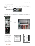
Page 19: ...the two thermostats ambiente and external to the elctric box of the Combi Block The power supply cable and the two thermostats should pass on the three electric gland placed on the back of the Combi B...

Page 20: ...elds and which require the greatest care are carried out at the panels It is necessary to place a damp fabric strip which must envelop the Thermoretractable Joint so that it is fuly protected from hig...

Page 21: ...trogen from the installation 5 3 7 Vacuum This operation is carried out using one load pipe that is located inside of the unit at the aspiration pipe During this operation the two hermetic valves shou...

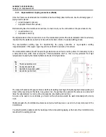
Page 22: ...state we run the risk that one of the components of the fluid will vaporize before the others and hence the installation will have a greater proportion of this component This is why the installation...

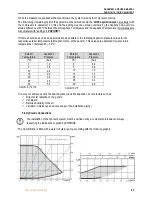
Page 23: ...temp at the panels This values are estimated for water return temperatures of between 25 30 C Exterior Temperature Aspiration Pressure C bar 0 1 2 5 1 6 10 2 2 15 2 9 20 3 6 25 4 5 30 5 5 You may not...

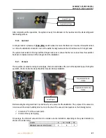
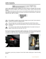
Page 24: ...with the existing equipment Firstly preferably choose heat emitters with a large exchange surface radiant flooring radiators convectors ventilo convectors as they allow distribution at a low temperatu...

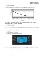
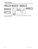
Page 25: ...ergie Combi System takes the form of a console whereby several operating settings can be configured such as Water outward and return temperature Temperature differentials Timers Typical ground plans o...

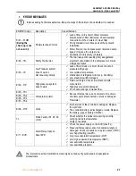
Page 26: ...6 12 16 Combi 12 HT 26 www energie pt For more information about the electronic panel please read the Energie Electronic Panel manual that is supplied with the equipment ERROR Code System Status Date...

Page 27: ...ruction of refrigerant circuit e g Humidity Low pressure switch damaged Er04 HP High pressure system doesn t work Fluid overcharge Check circuit pressure with manometers High pressure switch damaged P...

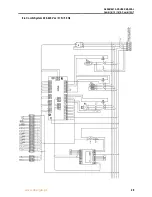
Page 28: ...ASSEMBLY AND USER MANUAL Combi 6 12 16 Combi 12 HT 28 www energie pt 8 ANNEXES A WIRING DIAGRAM 8 1 Combi System 220 240 Vac 1 N 50 Hz...

Page 29: ...ASSEMBLY AND USER MANUAL Combi 6 12 16 Combi 12 HT www energie pt 29 8 2 Combi System 400 420 Vac 3 N 50 Hz...

Page 30: ...sion Valve D tendeur Rc Resist ncia de C rter Crankcase Heater R sistance de carter SY250 Controlador Controller Contr leur HP Press stato de Alta High Pressure Switch Pressostat haute pression LP Pre...

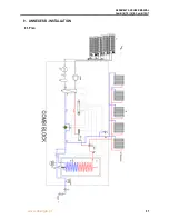
Page 31: ...ASSEMBLY AND USER MANUAL Combi 6 12 16 Combi 12 HT www energie pt 31 9 ANNEXES B INSTALLATION 9 1 Plan...

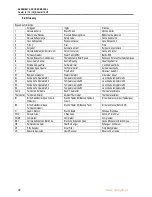
Page 32: ...tor 1 Circulateur d eau 1 S1 Sonda de Temperatura S1 Temperature probe S1 La sonde de temp rature S1 S2 Sonda de Temperatura S2 Temperature probe S2 La sonde de temp rature S2 S3 Sonda de Temperatura...

Page 33: ...used or assembled in accordance with manufacturer instructions or if there has been any form of intervention by unauthorized technicians has the appearance of modifications and or if the series number...

Page 34: ...ASSEMBLY AND USER MANUAL Combi 6 12 16 Combi 12 HT 34 www energie pt...

Page 35: ...Combi 6 12 16 Combi 12 HT www energie pt 35 ENERGIE EST LDA Zona Industrial de La ndos Lote 48 4570 311 La ndos P voa de Varzim Portugal Phone 351 252 600 230 Fax 351 252 600 239 E Mail energie energ...

Reviews: