7
PROBLEM
POSSIBLE CAUSES
REMARK
Fault in the electronic panel
Lack of power
Check for the presence of electrical power
Check the corresponding circuit breaker is turned on
Disconnected or damaged cabling
Check the electric or electronic circuit
Check the electrical protection (RES fuse)
Low water temperature
Equipment disconnected
Press the ON/OFF button
Absence of electrical current or damaged
cabling
Check the equipment is connected to the socket
Check the corresponding circuit breaker is turned on
Check the cabling
Check the power cable is disconnected from the electronic cable
Check the electrical protection (RES fuse)
Error in the performance of the
components
Check for errors on the electronic panel and consult the error
table
Temperature programmed on Setpoint low
Adjust the Setpoint temperature
Compressor disconnected
Turn on the compressor using the “COMP”
button
Hot water returning to the cold water
circuit (damaged or incorrectly installed
safety valve)
Close the cold water inflow valve to turn off the safety group.
Open a hot water tap. Wait for 10 minutes and if hot water is
available replace the defective pipe and/or correct the position of
the safety group.
Clean the safety group filter
Excessively hot water
Faulty gauge
Check for errors on ther electronic panel
Low hot water flow
Loss or blockage of the hydraulic circuit
Check the state of the hydraulic circuit
Water leaking from the safety
valve
Absence of or incorrectly-sized expansion
tank (if the leak is intermittent)
Installation and/or correct sizing of expansion tank
High network temperature (if leak is
continuous)
Check the pressure reduction valve (if present)
Install a pressure reduction valve (if absent)
Abnormally high constant
consumption of electricity
Loss or blockage in the cooling circuit
Check the tubing for damge
Use the appropriate equipment to check for leaks in the circuit
Adeverse weather conditions
Others
Contact customer service
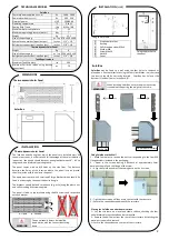
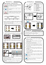
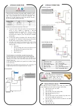
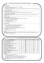
TROUBLESHOOTING
ERRORS
Error
Description
Possible Causes
LO
Probe
danificada
Disconnected or damaged probe
LP
Protection
system
activated
(low
pressure)
Insufficient load of refrigerant fluid
frigorigéneo
Refrigerant fluid leakage
Low outdoor temperature
Low water inlet temperature
Damaged low-pressure switch
Disconnected or damaged cabling
Damaged electronic panel
Error
Description
Possible Causes
HP
Protection
system
activated
(high
pressure)
Presence of air in the refrigerant circuit
Lack of water in the circuit
Damaged circulator pump
Dirty condensor/filter
(
if exists)
Excess fluid
Damaged high-pressure switch
Disconnected or damaged cabling
Damaged electronic panel
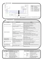
Legend:
Cp
Compressor
B1
Circulator Pump
Raux
Auxiliar Relay
EH
Backup Electric Heater
LP
Low Pressure Switch
HP
High Pressure Switch
S1
Temperature Probe
NOTE: “EH” is not included on the equipment. It’s the responsibility of the installer to
make its Installation
WIRING DIAGRAM


