background image


EMF5700


User


Manual


37


|


P a g e

Appendix


I:


Product


evaluation


kit


O

ffers


a


product


evaluation


kit,


including


a


digital


data


converter,


USB


data


cable,


and


User


Application


software,


that


allows


the


user


to


evaluate


the


product


performance


on


a


Microsoft


Windows

based


computer.


For


some


simple


applications


with


digital


data


transfer,


this


kit


could


serve


the


purpose.


The


user


can


read


and


visualize


the


flow


rate


of


the


product,


obtain


the


totalized


values,


and


save


the


data


for


further


analysis.


It


can


read


from


up


to


128


sensors


with


the


RS485


interface


in


serial.


For


further


information


and


purchase


of


the


evaluation


kit,


please


contact


the


manufacturer


or


the


sales


representative.


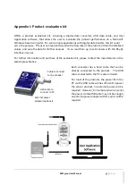
Each


converter


has


a


fixed


cable


that


can


be


directly


connected


to


the


product.


The


USB


cable


connected


to


the


PC


is


also


included.


For


most


of


the


products,


the


power


from


the


PC


via


the


USB


cable


will


be


sufficient


to


power


the


sensor


product,


no


external


power


will


be


required.


However,


for


multiple


sensors


in


serial,


the


power


via


the


USB


cable


may


not


be


enough,


an


external


power


adapter


with


8~24Vdc


will


be


required.


Cable to connect 
to the product 

USB cable to 
connect to PC  

External power 
adapter (optional)  

Summary of Contents for EMF5700

Page 1: ...Gas Mass Flow Meter VC 3 Model EMF5700 ...

Page 2: ...EMF5700 User Manual 1 P a g e Gas Mass Flow Meter with MEMS thermal sensing technology EMF5700 Series User Manual Document No 11 2021 MF2 EN Issue date 2021 11 Revision VC 3 ...

Page 3: ... environment Use this product according to the specified parameters Only the trained or qualified personnel shall be allowed to perform product services Be cautious for the electrical safety even it operates at a low voltage any electrical shock might lead to some unexpected damages The gas to be measured should be clean and free of particles Do not apply this meter for liquid medium Do not apply ...

Page 4: ...15 5 5 Meter MENU description 15 5 5 1 Starting the measurement 16 5 5 2 MENU entry with a verified password 16 5 5 3 Set the RS485 Modbus address 17 5 5 4 Set the RS485 communication baud rate 17 5 5 5 Reset or calibrate the offset 17 5 5 6 Gas conversion factor GCF for different gas measurement 18 5 5 7 Set the Response time 18 5 5 8 Select the display mode 19 5 5 9 Select the display language 1...

Page 5: ... 6 Product selection and order information 29 6 1 Product selection 29 6 2 Order contact and customer support 29 7 Technical specifications 30 8 Technical notes for the product performance 31 8 1 Measurement principle 31 8 2 Precautions for the best performance of the product 31 8 2 1 Comparison with a third party reference meter 31 8 2 2 Particle contamination and fluidic cleanness 32 8 2 3 Apply...

Page 6: ...the 3rd generation of the products having significantly upgraded features since its first release in 2010 The upgrade includes much improved accuracy an additional model to cover flow range and channel size compatibility significantly extended measurement dynamic range wireless data options and valve options The upgrade also ensures back compatibility for our existing customers This serial of prod...

Page 7: ...2 1 EMF5700 flow meter and accessories Please check immediately for the integrity of the product as well as the power and data cable if any abnormal is identified please notify the distributor sales representative or manufacturer as soon as you can If any defects are confirmed an exchange shall be arranged immediately via the original sales channel Note the LCD screen shall not be lighted until th...

Page 8: ...1 Product description Figure 3 1 EMF5700 parts description Figure 3 2 EMF5700 with valve Meter head rotatable Meter body LCD display MENU keys BSPP connector Flow direction Battery chamber cover Data and power port Installation screws ON OFF solenoid valve ...

Page 9: ...up or temperature if C lights up Flow The 2nd row Displays instant flow rate in L min Liters per minute or SCFH standard cubic feet per hour or m3 h cubic meters per hour Battery status Valve status The current product provides an ON OFF control valve LoRa wireless protocol is enabled when lights up NB IoT wireless protocol is enabled when lights up WIFI wireless protocol is enabled when lights up...

Page 10: ...a cable description Table 3 2 EMF5700 wire assignment Figure 3 4 EMF5700 cable USB C 100 3 4 Mechanical dimensions Figure 3 5 EMF5700 meter dimensions Wire Color Definition 1 Red Power supply 5 24 Vdc 2 Black GND ground 3 Green RS485A 4 White RS485B ...

Page 11: ...valves dimensions Table 3 3 Mechanical dimensions of the meters meters with control valves Connector G L1 L2 LV1 LV2 W1 W2 H1 H2 H3 EMF5706 BSPP 61 34 95 5 123 34 25 127 28 12 5 EMF5708 BSPP 3 8 81 45 110 134 45 30 134 35 15 5 EMF5712 BSPP 90 50 115 143 45 30 141 42 19 5 ...

Page 12: ...roduct is preferable to be installed horizontally Flow direction should be aligned with the arrow mark on the meter body If the flowing fluid may have particles or debris a filter is strongly recommended to be installed upstream of the meter Please follow the following steps to complete the installation Figure 4 1 EMF5700 meter installation a Upon opening the package the product s physical integri...

Page 13: ...larger than the flow channel pipe size of the meters to be installed For some typical situations please follow the installation recommendation detailed in the following sketches c 2x90 degree elbow 3 D d Pipe size reduction e Pipe size expansion f Control valve at upstream or downstream Figure 4 3 EMF5700 meter installation iii During installation please make sure no foreign materials such as wate...

Page 14: ...r is successfully connected the LCD should be lighted up with the proper information displayed works correctly g Slowly open the valve s if any upstream or downstream or both of the pipeline and the meter should then start to measure the flow in the pipeline Note because the meter has a large dynamical measurement range it could be normal if you see the small instant flow rate before you open the ...

Page 15: ... of the product it is advised that the gas to be measured must be clean and free of particles or other foreign materials 5 2 Check the leakage Check gas leakage before any measurement If it is needed the pressurized nitrogen or air can be used for the leakage check 5 3 Power the meter and digital data connection Although this product complies with the CE required EMC regulations it also requires t...

Page 16: ...t devices based on the Android system The APP provides the basic functions to access the meter sensor data plot an instant flow rate chart calculate totalized or accumulated flow volume at a specific time defined by the user It allows the user to send the local data instantly to a remote destination when the wired connection is not an option Also the interface provides the readout of the product i...

Page 17: ...the main display To enter a new password press the Up or Down key to change the digit that flashes and press the M key to confirm Repeat this process for all 5 digits and the meter will enter into the menu setting interfaces screen Subsequently the MENU allows the user to Set Modbus address F2 Addr Change communication baud rate F3 bPS Reset or calibrate the offset F11 oFFST Enter the gas conversi...

Page 18: ...M key to set the RS485 communication baud rate There are 6 baud rates selectable depending on your system requirements 4800 9600 19200 38400 57600 and 115200 The default baud rate is 9600 Use the Up or Down key to select the desired one and press the M key to confirm The display will then return to the F3 bPS screen which indicates the task is completed Use the Up or Down key to select F99 qUIT an...

Page 19: ... contact the manufacturer before further proceeding Following the above mentioned steps at the MENU setting screen use the Up or Down key to select F12 GCF Press the M key to confirm and it will open the sub MENU showing the current gas conversion value Usethe Up or Down and the M confirmingkey to input the desiredvalue and press the M key again to complete the task The display will then return to...

Page 20: ...lt languages following the above mentioned steps at the MENU setting screen use the Up or Down key to select F39 LAnG Press the M key to confirm and it will open the sub MENU showing the current language Use the Up or Down and the M confirming key to select the desired one and press the M key again to complete the task The display will then return to the F39 LAnG screen which indicates the task is...

Page 21: ...tes the task is completed Use the Up or Down key to select F99 qUIT and the M key to exit the MENU and return to the Main Display screen 5 5 12 Set an alarm lower instant flow rate limit This function allows the user to set the instant flow rate below which the meter will trigger the alarm function The alarm will be a sharp sound every 2 seconds whiling the screen display will flash The triggered ...

Page 22: ...play will then return to the F53 ALm A screen which indicates the task is completed Use the Up or Down key to select F99 qUIT and the M key to exit the MENU and return to the Main Display screen 5 5 14Change the default password For data safety it is recommended that the default password of 11111 should be changed when the first use of this product Following the above mentioned steps at the MENU s...

Page 23: ... Display screen 5 5 16Exit the MENU At the MENU settings use the Up or Down key to select the F99 qUIT option and press the M confirming key to exit the MENU settings and return to the Main Display screen 5 5 17 Sleeping mode When the meter is powered by batteries it is necessary to enable the sleeping mode for the power saving to allow a longer operation time The meter is programmed with an autom...

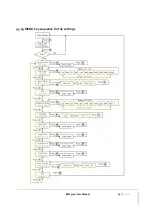
Page 24: ...EMF5700 User Manual 23 P a g e 5 5 19MENU key sequence for the settings ...

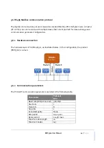
Page 25: ...parameter configuration 5 6 1 Hardware connection The hardware layer is TIA EIA 485 A as illustrated below In this configuration the product EMF5700 is a slave 5 6 2 Communication parameters The PC UART communication parameters are listed in the following table Parameters Protocol RTU Baud rate Bits per second 9600 bps Start bits 1 Data bits 8 Stop bits 1 Even Odd parity None Bits period 104 2 µse...

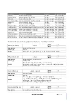
Page 26: ... codes applied for the product are the sub class of the standard Modbus function codes These codes are used to set or read the registers of the product Code Name Functions 0x03 Read register Read register s 0x06 Set single register Write one single 16 bit register 0x10 Set multiple registers Write multiple registers 5 6 5 Registers The product EMF5700 has multiple registers available for the assig...

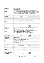
Page 27: ...er Reset accumulated or totalized flow rate W 0x00F2 40243 0x00F2 Write protection Write protection of selected parameters W 0x00FF 40256 0x00FF The detailed information of each register is described below Y enabled N disabled Flowmeter address 0x0081 Write Y Read Y Description Address of the product Value type UINT 16 Notes Values from 1 to 255 except for 157 0x9d 0 is the broadcast address SN Se...

Page 28: ...gas that is different from the calibration gas Value type UINT 16 Notes The air default is 1000 normally read from register 0x008B The product will disable this function with write protection once the metering gas is confirmed with the proper GCF For a specific GCF value please contact the manufacturer Response time 0x008D Write Y Read Y Description Set response time Value type UINT 16 Notes 125 2...

Page 29: ...et Value type UINT 16 Fixed value 0xAA55 Notes To reset or calibrate the offset write 0xAA55 to register 0x00F0 When you execute this function make sure there is NO flow in the flow channel Reset accumulated flow rate 0x00F2 Write Y Read N Description Reset the accumulated or totalized flow rate value Value type UINT 16 Fixed value 0x0001 Notes To reset the accumulated or totalized flow rate value...

Page 30: ... distributors representatives are listed at the end of this document For small quantities the order can be placed either through the Energometrika website www energometrika ru or the sales office For large quantities please contact the sales office distributors or sales representatives Energometrika is making every effort to ensure the quality of the products In case of questions and or product su...

Page 31: ...ure 10 55 C Maximum pressure 0 8 MPa Humidity 95 no condensation RH Maximum overflow 100 200 400 SLPM Maximum flow change 15 30 60 SLPM sec Pressure loss 0 6 1 0 2 0 kPa Power supply 4 AA batteries LR6 5 24 Vdc Power consumption 60 on batteries day Power data interface USB Type C Digital output RS485 Modbus half duplex Wireless options LoRa WIFI NB IoT BT LE Display LCD Resolution 0 01 L min insta...

Page 32: ...f the membrane at various fluidic pressure conditions the calorimetric thermal sensing will guarantee a pressure and temperature independent mass flow data acquisition The MEMS technology also allows the mass production of the sensing elements that significantly reduces the cost compared to a traditional thermal mass flow sensing element It enables the current offer with superior value to the user...

Page 33: ...ant to ensure the applied flow medium will be clean and dry If any contamination is suspected please allow experienced technical personnel to have it checked and re conditioned Do not use a foreign cleanser or other fluids to clean the flow path which could bring irrecoverable damage 8 2 3 Apply to a different gas medium The product is calibrated with a high precision NIST traceable metrological s...

Page 34: ...er regulator failure Return to factory Sensor failure Return to factory Large errors or unexpected flowrate Particles fluid type Check system Erroneous or large noise Vibration unstable flow Check system Valve not work Wire connection valve Return to factory Offset unstable Circuitry instability Check system power off No digital interface Wrong address software Check commands connection No wireles...

Page 35: ...tion etc other consequential or indirect damages of any kind To the extent permitted by law the exclusive remedy of the user or purchaser and the limit of Siargo s liability for any and all losses injuries or damages concerning the products including claims based on contract negligence tort strict liability or otherwise shall be the return of products to Energometrika and upon verification of Ener...

Page 36: ...ed for whatever reasons 4 Products that have been subject to working conditions beyond the technical specification as described by this manual or related datasheet published by the manufacturer 5 Any damages incurred by the incorrect usage of the products 6 Energometrika does not provide any warranty on finished goods manufactured by others Only the original manufacturer s warranty applies 7 Produ...

Page 37: ...lity of the products In case of questions and or product supports please contact customer service at the address listed below We will respond to your request in a timely fashion and will work with you toward your complete satisfaction Customer service and all orders should be addressed to ...

Page 38: ... can read from up to 128 sensors with the RS485 interface in serial For further information and purchase of the evaluation kit please contact the manufacturer or the sales representative Each converter has a fixed cable that can be directly connected to the product The USB cable connected to the PC is also included For most of the products the power from the PC via the USB cable will be sufficient...

Page 39: ...y Revision C 3 November 2021 Added the response time setting Corrections Revision C 2 July 2021 Corrections Revision C 1 March 2021 The formal release of the 3rd generation products Revision C 0 Sepetember 2020 The first release of the 3rd generation products ...

Reviews: