background image

Product Manual


- 7 -

Notes: 

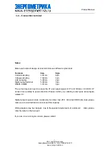
Meter use foolproof design, access terminal uses different styles block: 

Terminal 

Size 

Style 

Current sampling 

3.81mm 

6pin 

Voltage sampling 

7.62mm 

4pin 

AUX sampling 

5.08mm 

2pin 

Digital output terminal 

5.08mm 

3pin 

RS485 COMM 

3.81mm 

3pin 

The current input pin need to access the CT, and output signal of CT is 0-100mA or 0~0.333V, CT 

access  have  polarity  to  power  direction.  Please  confirm  your  ordering  meter  types  and  prepare 

related CT. 

Digital output is passive load, inside relay can drive max 250

VAC(3A)/30VDC(3A) load, please 

make sure connected load do not exceed this capacity. 

Wiring diagram may be changed 

due to the special requirements of customers’  order, please 

refer the label on the rear part. 

If you are or sure or signs unclear, please contact: 

3.2. - Connection terminal 

ООО «Энергометрика»,

zakaz@energometrika.ru, тел.:+7(495)276-0510

www.energometrika.ru

Summary of Contents for EnergoM 400

Page 1: ...Product Manual Multi channel Circuit Metering System User Manual Version 1 2 EnergoM 400 www energometrika ru zakaz energometrika ru 7 495 276 0510...

Page 2: ...t the scene 1 Before the meter turning on the power supply be sure that the p ower supply within the provisions of the instrument 2 When installation the current input terminal must non open voltage i...

Page 3: ...L OF 7 4 SETUP PROCEDURE 8 4 1 KEY OPERATION 8 4 2 SHOW ELECTRIC PARAMETERS 8 4 3 PARAMETERS SETTING 10 4 4 MENU STRUCTURE 11 5 COMMUNICATION PROTOCOL 13 5 1 CONNECTION FOR THE RS485 BUS 13 5 2 MODBUS...

Page 4: ...d for per channel Frequency System Frequency Energy Function Energy kWh measurement meeting international standards accuracy is Class 1 0 It optional Time of Use feature 12 Seasons 4 Tariffs record ma...

Page 5: ...ccuracy depends one sampling CT and PT accuracy Input Voltage Rated 20 380V need confirm before order Current Rated 100mA optional 0 333V need confirm before order Frequency 40 65Hz Overload Current 1...

Page 6: ...ity RH 20 95 No condensation Storage Conditions Temperature 30C 70C Humidity RH 20 95 Working Power AC DC 85 265V 45 65Hz Maximum power consumption3W Dimensions L H D 105X104X61 75mm zakaz energometri...

Page 7: ...ages the instrument must be immediately powered off In thiscase contact a qualified service representative 3 1 Installation Mounting Instrument is to be mounted on35mm Din rail Keep all connections in...

Page 8: ...0 100mA or 0 0 333V CT access have polarity to power direction Please confirm your ordering meter types and prepare related CT Digital output is passive load inside relay can drive max 250 VAC 3A 30V...

Page 9: ...change 4 2 Show electric parameters parameters press to switch another screen in this channel press to switch parameter for channel 1 4 press to switch more details parameter in screen screen roller l...

Page 10: ...Product Manual 9 www energometrika ru zakaz energometrika ru 7 495 276 0510...

Page 11: ...required variables Press the key SET can enter the parameter setting the screen ask access password Default is 0001 then press can enter the menu The operation menu logic as following The SETUP proced...

Page 12: ...efault is 9600 Check format n 8 1 o 8 1 e 8 1 Factory default n 8 1 Alarm Setting Alarm_1 5 Mode OFF Upper Limit Lower Limit Total three mode Delay Alarm triggered time delay Default 001 0s Parameter...

Page 13: ...al 12 Backlight 1 5 LCD backlight duration unit is min default is 5 Clear Energy Clear the record in meter Contrast 1 9 LCD display contrast default is 5 zakaz energometrika ru 7 495 276 0510 www ener...

Page 14: ...een the BJ194 and the master unit This Bus may connect a maximum of 32 BJ194 Note 1 For communication with the master unit customers can choose the RS 232 to RS 485 converter to use 2 Full range of BJ...

Page 15: ...tarting address low byte Number of registers high byte Number of registers low byte Error Check code 2 BYTE Cyclical Redundancy Check CRC MODBUS FUNCTIONS Code Meaning Description FUNCTION 03 Reading...

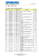
Page 16: ..._Q float 2 Channel_1 Total reactive power Unit kVar R 34 CH1_Sa float 2 Channel_1 Individual apparent power Unit kVA R 36 CH1_Sb float 2 R 38 CH1_Sc float 2 R 40 CH1_S float 2 Channel_1 Total apparent...

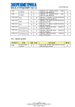
Page 17: ...ergy Unit kVarh R 82 CH1_EqC float 2 Channel_1 C phase negative reactive energy Unit kWh R 100 182 CH2_parameter float 2 Channel_2 parameter structure refer to Channel_1 R 200 282 CH3_parameter float...

Page 18: ...oltage even harmonic total distortion unit 0 1 R 1307 TEHDUb int 1 B phase Voltage even harmonic total distortion R 1308 TEHDUc int 1 C phase Voltage even harmonic total distortion R 1320 1339 HUa int...

Page 19: ...479 Hic1 int 20 Channel_1 C phase Current harmonic ratio for 2 to 21th R 1500 1579 CH2 Harmonic int 20 Channel_2 harmonic value structure refer to Channel_1 R 1600 1679 CH3 Harmonic int 20 Channel_3 h...

Page 20: ...NANCE or repairing action should be done when the instrument open and powered on should those actions are essential high qualified operators must perform them Before any adjustment replacement mainten...

Reviews: