background image


Operating Manual 


96 

Arc fault 

protection ZŁ-4A; (07.2019) 


15.3. Detection and elimination of the damage 

The device possesses the self-diagnostics system that provides instantaneous signaling 

of  most  of  inner  failures.  After  detecting  a  failure  by  the  self-diagnostics  system  or  by  the 

personnel  it  is  necessary  to  describe  symptoms  of  the  failure  and  to  consult  them  with  the 

representative of the producer service in order to obtain instructions for further procedure. It 

is not recommended to make any repairs by the user without previous arrangement with the 

producer of the device. 


16. Storing 

Transport  packaging  should  have  the  same  vibrations  and  strokes  endurance  as  it  is 

specified in standards PN-EN 60255-21-1:1999 and PN-EN 60255-21-2:2000 for the sharp-

ness of the class 1. 

The  device  delivered  by  the  producer  should  be  unpacked  carefully  not  with  use  of  too 

much  strength  and  not  adequate  tools.  After  unpacking  it  should  be  visually  checked  if  the 

device has no external damage. 

The device should be stored in a dry and clean place. The temperature of the storage is 

in the range from 

25

C up to +70

C. 

Relative  humidity  should  be  in  such  a  range  that  condensation  and  hoarfrost  would  not 

occur. 

The devices should be installed at their workplaces about 2 hours before supplying. It is 

necessary to equalize temperature and to avoid humidity and condensation. 


17. Utilization 

If it is necessary to disassemble the device (and  eventually remove it) as the result of a 

damage  or  the  end  of  its  operation  life  time,  all  the  supplying  and  measurement  units  and 

other connections should be switched off before. 

The disassembled device should be treated as electronic scrap which undergoes appro-

priate regulations concerning waste management. 


Summary of Contents for ZL-4A

Page 1: ...is design may be copied and distributed only as a whole Copying and or use part of this design for may take place only upon a written permission issued by Energotest Ltd ARC FAULT PROTECTION ZŁ 4A Operating Manual Gliwice July 2019 ...

Page 2: ...Arc fault protection ZŁ 4A 07 2019 Documentation version Table of contents points Description IU_ZŁ 4A ANG 20181127 Original version IU_ZŁ 4A ANG 20190710 Addition of records about the maximum length of the fiber re serve ...

Page 3: ...of products mentioned in this instruction are producer s brand and should be considered as registered trademarks To contact us Energotest sp z o o ul Chorzowska 44B 44 100 Gliwice Poland Phone Central office 048 32 270 45 18 Phone Production Department 048 32 270 45 18 ext 40 Phone Marketing 048 32 270 45 18 ext 26 Fax 048 32 270 45 17 E mail Production Department produkcja energotest com pl Inter...

Page 4: ... deliver them This may help us to make the manual easier to be used and give consideration to wishes and requirements of the users A device to which the manual has been prepared does not cover all potential dangers to people and material value That is why every person working with this device or performing any activities connected with operating and service of the device has to be previously train...

Page 5: ...upply 16 5 3 ZŁ 4A front panels 17 5 3 1 Central unit 17 5 3 2 Bay unit 18 5 3 3 Executive unit 19 6 Technical data 20 7 List of applied standards 27 8 Information on completeness 28 9 Mounting 28 10 Starting up 37 10 1 Registration of bay units 37 10 2 Optical inputs configuration 38 10 3 Optical inputs checking 38 10 3 1 Check with an external light source 38 10 3 2 Check with an embedded test 3...

Page 6: ...l menu structure 52 13 3 Menu pages review 53 13 3 1 Page 1 JP JW UNITS 53 13 3 2 Page 2 STATUS 59 13 3 3 Page 3 ACTIVATION 62 13 3 4 Page 4 OCCURRENCES 64 13 3 5 Page 5 TRIPPING 65 13 3 6 Page 6 ALARMS 67 13 3 7 Page 7 CONFIGURATION 69 13 3 8 Page 8 OPTICAL SYSTEM TEST 77 14 Communication ports 82 14 1 CAN bus 82 14 2 RS485 Interface 82 15 Operating 95 15 1 Periodic check of the protection operat...

Page 7: ...N 60255 26 2014 01 for the EMC directive 3 Application of the unit The majority of faults in medium or low voltage switchgears are accompanied by an elec tric arc which causes significant damage to equipment and is a great hazard to human life Breaking a fault within up to 100 ms enables the avoidance of the most serious damage to equipment and decreases a hazard to people in the vicinity of the p...

Page 8: ...sonnel and the equipment against destructive effects of arc faults 4 Safety rules The following chapter presents the information crucial to appropriate installation and op eration of the product It is assumed that the personnel installing and operating this device is properly qualified and is aware of the potential danger of electrical devices The device fulfills all the requirements of obligatory...

Page 9: ...rized and acquainted with operat ing manuals Opening the casing Before starting any activities that require opening the device casing one should obligatorily switch off all the measurement and auxiliary voltage supplies and disconnect all terminals blocks The dangerous voltage may appear on the de vice elements during 1 min after isolating the circuit The applied integrated circuits are very sensi...

Page 10: ... cause hazard to users and eventually result in incorrect function ing Energotest does not take any responsibility for damage caused by applying inappropriate elements or components of the device Nominal data name plates and stickers It is obligatory to obey instructions located on the device such as descriptions or name plates and stickers and it is necessary to keep them legible Plates and stick...

Page 11: ...from a power supply suggested by the manufacturer supplied from the guaran teed 220V DC or 230V AC A bay unit should be installed in every bay of the switchgear i e incoming feeder out going coupling voltage measurement bays etc Each bay unit is equipped with 4 optic de tectors that can be installed differently depending on a particular application the only re quirement is to maintain protection o...

Page 12: ...ptical module and voltage module in zone 2 results in activation of tripping signal to open the circuit breaker in the cur rent bay selective activation Other circuit breakers in the protected switchgear remain closed Signal indicating a detection of the arc fault in zone 2 is transmitted also to the cen tral unit that activates proper actuator relays zone 3 S3 includes cable connection and circui...

Page 13: ...p units in the system are 5 ZŁ 4A protection can consist of maximal 99 bay units and 5 executive units connected to one central unit Total length of CAN bus should be less than 250 meters There are availa ble technical solutions using fiber optic converter which enable the increase of the length of the CAN bus Delays of the device tripping associated with these solutions are negligible Energotest ...

Page 14: ...lays associating them to the protection zones detection of voltage drop in the switchgear distribution of the voltage drop signal to bay units reading information on settings and activation of bay units controlling data transmission generation of tripping signals by the output relays to the feeder of protected switchgear and of signals of ATS blockade generation of alarm signals in case of incorre...

Page 15: ...eceiving signal of arc fault in zone 1 from other bay unit generation of alarm signals indicating wrong functioning of the device testing optical detectors Bay unit ZŁ 4A JP is built with optical signalization 3 LEDs operation panel alphanumerical display and 4 buttons CAN terminal block 4 optical inputs for optical detectors 4 optical outputs for optical detectors 1 executive relay with closing c...

Page 16: ...tor allows one for fiber integrity testing Maximum length of a fiber optic cable for a point sensor is 15 m while for the fiber optic loop it is 5 m Detectors delivered by Energotest are ready for installation 5 2 5 Power supply A power supply can be connected to the guaranteed 220V DC or 230V AC and is a source of 24V DC for all the elements of the protection Each unit system consisting of a cent...

Page 17: ...en a temporary activation of the optical module U MODULE ACTIVE indicates that voltage module has been activated and there is a voltage drop in the switchgear TRIPPING indicates that ZŁ 4A protection has generated a tripping signal af ter an arc fault detection RELAY EXE indicates activation of an executive relay programmed by the us er default LED activation in case of an activation of any execut...

Page 18: ...or code are displayed on LCD display TRIPPING indicates that ZŁ 4A protection has generated a tripping signal af ter an arc fault detection two digit seven segment LED display indicates a state of the bay unit allows one to change a configuration of the unit 4 buttons for operation of the panel control UP increasing the value or menu scrolling DOWN decreasing the value or menu scrolling ENTER sett...

Page 19: ...er supply voltage ERROR indicates malfunctioning of the device TRIPPING indicates that unit has generated a tripping signal two digit seven segment LED display indicates a state of the executive unit allows one to change a configuration of the unit 4 buttons for operation of the panel control UP increasing the value DOWN decreasing the value ENTER settings approval enter into menu mode ESC DEL tri...

Page 20: ...ng and signaling Max contact voltage 440 V AC 250 V DC Max continuous current Max power AC1 8 A 2000 VA Time Up to the contact closing 8 ms Insulation electrical Circuit insulation rated voltage 250 V Electrical strength of insulation 2 kV 50 Hz 1 min Between opened relay contacts 500 V 50 Hz 1 min Environmental conditions Rated temperature Temperature limits Humidity Atmospheric pressure 10 55 o ...

Page 21: ...ation electrical Circuit rated insulation voltage 250 V Electrical strength of insulation 2 kV 50 Hz 1min Between opened relay contacts 500 V 50Hz 1min Environmental conditions Rated temperature Temperature limits Humidity Atmospheric pressure 10 55 o C 25 and 70 o C 45 75 86 106 kPa Vibrations endurance 1st class PN EN 60255 21 1 Electromagnetic compatibility EMC Test class Max power supply break...

Page 22: ...500 VA Time Up to the tripping contact closing 8 ms Insulation electrical Circuit rated insulation voltage 250 V Electrical strength of insulation 2 kV 50 Hz 1min Between opened relay contacts 500 V 50Hz 1min Environmental conditions Rated temperature Temperature limits Humidity Atmospheric pressure 10 55 oC 25 and 70 oC 45 75 86 106 kPa Vibrations endurance 1st class PN EN 60255 21 1 Electromagne...

Page 23: ...iameter 2 2 x 4 4 mm Bending radius 25 mm Rated temperature limits 50 70o C Max tensile strength 5 N Length max 15 m Max fiber reserve 1 m Type Fiber loop detector External diameter 1 mm Bending radius 25 mm Rated temperature limits 50 70o C Max tensile strength 5 N Length max 5 m Max fiber reserve 1 m ...

Page 24: ...Operating Manual 24 Arc fault protection ZŁ 4A 07 2019 Fig 5 ZŁ 4A JC dimensions ...

Page 25: ...Operating Manual Arc fault protection ZŁ 4A 07 2019 25 Fig 6 ZŁ 4A JP dimensions ...

Page 26: ...Operating Manual 26 Arc fault protection ZŁ 4A 07 2019 Fig 7 ZŁ 4A JW dimensions ...

Page 27: ...or in stalling operating and maintenance of the device The arc protection type ZŁ 4A fulfills all the standards specified in respective directives low voltage and electromagnetic compatibility in accordance with harmonized standards mentioned below PN EN 60255 27 2014 06 Measuring relays and protection equipment Part 27 Product safety requirements harmonized with LVD directive PN EN 60255 26 2014 ...

Page 28: ...st plugging in the device should be placed in the room it is going to be installed for at least two hours This action is intended to compensate the temperature and avoid humidity All units of the arc fault protections type ZŁ 4A are dedicated to be mounted on rails type TS 35 inside relay compartments of the protected switchgear It is recommended to locate ZŁ 4A JP bay units in such a place where ...

Page 29: ...sted pair cable One pair of cables is used for power supply 24V DC and the other is used for data trans mission CAN Connections between elements can be organized as a chain structure with or without the use of intermediate terminals Cable length between clamps in the terminal and the bay executive unit should be shorter than 0 5 meter Respective connections are pre sented in figures Fig 10 Fig 12 ...

Page 30: ...lamps A8 for JP JW B2 for JC with CAN H line In case of the last unit in a chain the terminator should be activated by closing contacts CAN RL CAN RH CAN R A5 A6 A7 for JP B3 B4 B5 for JC Connections diagram of several ZŁ 4A devices is presented in figures Fig 14 Fig 15 and Fig 16 The cable screen should be connected to the PE clamp in the place of the JC installation In other places the screen sh...

Page 31: ...Operating Manual Arc fault protection ZŁ 4A 07 2019 31 Fig 12 Detailed diagram of ZŁ 4A elements connections chain without an intermediate terminal ...

Page 32: ...Operating Manual 32 Arc fault protection ZŁ 4A 07 2019 Fig 13 Detailed diagram of ZŁ 4A elements connections chain with an intermediate terminal ...

Page 33: ...Operating Manual Arc fault protection ZŁ 4A 07 2019 33 Fig 14 ZŁ 4A JC external circuit connection ...

Page 34: ...Operating Manual 34 Arc fault protection ZŁ 4A 07 2019 Fig 15 ZŁ 4A JP external circuit connection Fig 16 ZŁ 4A JW external circuit connection ...

Page 35: ...rect mounting of optic elements of the device in particular conservation of safe bend radius for fiber optic arrangement of fiber optic in such places where the damage during routine mainte nance work is highly unlikely keeping clear of moving parts of the switchgear drives pulling elements of interlocks limit switches etc if possible laying the fiber optics independently apart from other conducto...

Page 36: ...Operating Manual 36 Arc fault protection ZŁ 4A 07 2019 Fig 17 Detailed diagram of ZŁ 4A elements connections chain without an intermediate ter minal with CAN FO converter and executive unit ...

Page 37: ...ary for a proper operation of the protection system In order to register bay and executive units in the central unit please follow point 13 3 7 Fig 44 by choosing option SCAN INSTALL Then this step is made automatically by the central unit Each network address of respective bay and executive units can be found on the page 1 JP JW UNITS in REGISTERED Sub menu There is a possibility to add or remove...

Page 38: ...ssage on a temporary acti vation will be visible also on page 3 ACTIVATION of the central unit operation panel OPT MODULE ACTIVE LED will be illuminated with pulsed light During continuous lighting on the sensor after 5 s the inputs will become permanently blocked and ERROR LED will light both on JP and JC OPT MODULE ACTIVE LED will light steadily Detailed information on the activation will be ava...

Page 39: ...il next test run or until being cleared by pressing button In order to run tests of optical system from the level of the bay unit JP one needs to follow instructions given in 11 6 of this manual The test result is visible on the front panel of the tested bay unit JP as well as on the operating panel of the central unit JC The bay unit JP makes information about which of the optical system is damag...

Page 40: ...ly 11 Using of ZŁ 4A JP control panel 11 1 Information on software version Immediately after power supply connecting all the LED s and all the segments of the dis play are illuminated After a few seconds an actual software version number will be dis played A full number is displayed in two stages Fig 18 because the display has only two digits Fig 18 Actual software version Next the bay unit will r...

Page 41: ... checked in this mode see Fig 21 It is possible after pressing or button Information on the display Digit number of an optical input L low state of an optical input light detector not activated H high state of an optical input light detector continuously activated Pulsing L information that the light detector has been temporarily activated but at the moment it is not activated r the executive rela...

Page 42: ...Operating Manual 42 Arc fault protection ZŁ 4A 07 2019 Fig 21 Information on JP control panel states of optical inputs and executive relay ...

Page 43: ...the settings the voltage module U will be activated A respective detection is made in central unit and a proper message is sent to all the bay units through CAN bus A pulsing message UL is shown on the front panels of bay units Fig 22 The device changes its mode into single criterion mode In such a situation a light detecting results in a tripping signal generation Fig 22 Voltage drop message ...

Page 44: ...lt protection ZŁ 4A 07 2019 11 3 Bay unit configuration In order to enter into the configuration mode press button for 3 s After that the con figurable parameters will be displayed one by one see Fig 23 Fig 23 Configuration mode ...

Page 45: ...t The bay unit works in single criterion mode A tripping signal is generated in case of an optical module activation U module activation may not checked Tripping is only possible in zone 2 and in zone 1 isolated operation E2 permanent activation of the optical module activation of one of the optical detectors for longer than 5 s The protection does not detect any voltage drop The detection channel...

Page 46: ...ording to the estab lished regime On the front panel of JP TRIPPING LED is lighted and information in which protected zone the arc fault has been detected is displayed on the LCD display In case when a voltage drop or a voltage fall has appeared on the busbars of the switch gear the information UL will be displayed The messages are displayed cyclically by blink ing light Fig 24 and Fig 25 Fig 24 M...

Page 47: ...ective message is displayed even in case of lack of communication with JC JPs change their mode into sin gle criterion mode Deleting TRIPPING is realized by pressing button on the front panel of a bay unit for longer than 3s The tripping of a bay unit s executive relay is deleted Deletion of activation or tripping of all elements of the protection system is realized by pressing button on the front...

Page 48: ... unit In order to perform such test one needs to press the but ton as soon as the following symbol appears on the screen of the bay unit panel The results of the test are visible on the bay unit panel for 30 s and until being deleted on the page 8 OPTICAL SEN TEST of the central unit operating panel The way the results are presented is shown in Fig 26 Fig 26 Presentation of the optical detectors t...

Page 49: ...ig 27 Actual software version Next the executive unit will revert to ready status and its network address is visible on the display under the condition that it has been configured Fig 28 Message displayed for a executive unit without a network address In case when a executive unit does not have a configured network address symbol will be displayed Standard setting is number r1 Fig 29 Information d...

Page 50: ...ages In case when a executive unit will detect wrong operation of the device error number will be shown on the display E1 no communication with the central unit The executive unit will not generated a tripping signal E2 not applicable E3 an executive unit has its network address configured incorrectly A physical connection through CAN interface is correct It is necessary to register this executive...

Page 51: ... activation or tripping of all elements of the protection system is realized by pressing button on the front panel of a central unit for longer than 3s Information about the protection system tripping is signalized on the front panel and also by closing the contact of the signaling relay contacts F5 F6 are closed of JC the default con figuration Detailed information is available on the page 5 TRIP...

Page 52: ...The control panel menu has a tree structure with branches The name of the current menu or the submenu with its number and the list of available submenus are presented in the headline on the display see Fig 32 A submenu can have a variable providing infor mation about present status of the protection system This parameter is then presented in the submenu s headline after symbol Scrolling to main pa...

Page 53: ... 2019 53 Fig 32 Scrolling between main menus pages Fig 33 Submenu selection 13 3 Menu pages review 13 3 1 Page 1 JP JW UNITS On the page 1 JP JW UNITS there is information presented on the bay JP and executive JW units registered by the user in JC ...

Page 54: ...cified JP JW Information about a certain JP JW is available in different menus after entering its network address It is possible to view various parameters of JP JW submenu without another net work address entering from the overriding menu In this case is necessary to press but ton The specified submenu is switched between units JP has the following parameters which are grouped in six submenus Sub...

Page 55: ... Submenu SETTINGS SENSORS it shows the current configuration of the optical inputs The optical inputs are denoted by numbers from 1 to 4 The present configuration of the specified optical input is showed below the number There are the following optical input configurations possible S1 optical input is assigned to zone 1 S2 optical input is assigned to zone 2 S3 optical input is assigned to zone 3 ...

Page 56: ...Operating Manual 56 Arc fault protection ZŁ 4A 07 2019 Fig 34 Viewing available information about JP ...

Page 57: ...there is an address conflict in the network Submenu TRIPPING NOT APPLICABLE Submenu LOG STATE RELAY it presents the current status of JW executive relay There are the following executive relay statuses possible L inactivated relay the contact of the relay is opened H activated relay the contact of the relay is closed Submenu SETTINGS NOT APPLICABLE Submenu TEST RESULT NOT APPLICABLE Information ab...

Page 58: ...Operating Manual 58 Arc fault protection ZŁ 4A 07 2019 Fig 35 Viewing available information about JW ...

Page 59: ...igned to zone 1 ZONE S2 00 it shows information about the amount of the units with the optical detector assigned to zone 2 ZONE S3 00 it shows information about the amount of the units with the optical detector assigned to zone 3 Submenu JC UNIT RELAYS 00 This submenu shows the amount of the JC activated executive relays After selecting this submenu by pressing button the user receives detailed in...

Page 60: ... an arc fault detection in zone S2 S3 relay contact is closed after an arc fault detection in zone S3 S relay contact is closed after an arc fault detection in any zone U relay contact is closed after a voltage drop or a lack of voltage detec tion LG relay contact is closed according to the logical function created by a user details about creating logical functions are described in point 13 3 7 re...

Page 61: ...Operating Manual Arc fault protection ZŁ 4A 07 2019 61 Fig 36 Page 2 STATUS using ...

Page 62: ...input has been permanently activated Submenu DETECTION U This submenu shows whether the voltage module U has been activated After entering the submenu momentary or permanent act the list of JP network ad dresses of the selected criteria is presented Users have access to detailed information by selecting a certain JP network address and after accepting it by pressing button Fig 37 shows the case wh...

Page 63: ...Operating Manual Arc fault protection ZŁ 4A 07 2019 63 Fig 37 Analysis of optical module temporary activation ...

Page 64: ...enerated a trip ping signal in zone S2 Submenu IN ZONE S3 This submenu displays information about the amount of units which have generated a trip ping signal in zone S3 After entering the menu similarly to other main pages there is the list of JP network ad dresses of the selected criteria Users have access to detailed information by selecting the JP network address and accepting it by pressing bu...

Page 65: ... units which have generated a trip ping signal in zone S2 Submenu IN ZONE S3 This submenu displays information about the amount of units which have generated a trip ping signal in zone S3 After entering the submenu similarly as it is on other main pages there is a list of JP net work addresses which are subjected to a specified criterion User has an access to detailed information by selecting the ...

Page 66: ...ing Manual 66 Arc fault protection ZŁ 4A 07 2019 Fig 38 Analysis of tripping signals which have been generated in zone S1 by JPs with net work addresses 07 and 15 and in zone S2 by JP with network address 18 ...

Page 67: ...network address conflict change of the JP or JW network address without re registration change of the JP or JW network address for an address already existing in the network Submenu OPT SENSOR FAIL This menu informs about the number of units in which optical system error has been detect ed After entering this submenu there is a list of JP or JW network addresses presented which follow a selected c...

Page 68: ...Operating Manual 68 Arc fault protection ZŁ 4A 07 2019 Fig 39 Location of a permanently activated optical input ...

Page 69: ... are denoted by symbols from P1 to P6 Selecting a relay is done by pressing button The function which determines the relay tripping is cho sen by button There are the following functions describing the tripping of relays available S1 contact relay is closed after an arc fault detection in zone S1 S2 contact relay is closed after an arc fault detection in zone S2 S3 contact relay is closed after an...

Page 70: ...function LG it is necessary to enable the realization of this function The syntax describing the logical function is based on selection of the specified JPs detector with a correct way of tripping Then the function cre ated by the user is a logical sum of the selected JPs detectors in particular zones The idea of creating a function LG is presented in Fig 41 ...

Page 71: ...C executive relays P1 P5 connected with zone S1 executive contact relay is closed after an arc fault detection in zone S1 P6 S connected with zones S1 S2 S3 executive contact relay is closed after an arc fault detection in any zone JC is equipped with a configurable signal diode RELAY EXE Illumination of the LED can be connected with JC executive relays tripping There are the following settings av...

Page 72: ...configuration of signalization diode RELAY EXE L1 P LED signalizes that any relay is closed Fig 42 Configuration of the logical function LG Contact of relay P2 is closed if JC 07 opti cal detector has been activated and had been configured before to work in zone S1 ...

Page 73: ... which has been configured by the user from the list The choice is accepted by pressing button Fig 43 DELETE UNIT it allows one to delete a unit from the system unregistering The unit is deleted from the system by selecting the network address from the displayed list The choice is accepted by pressing button Fig 43 SCAN INSTALL after selection of this mode JC automatically searches through the net...

Page 74: ...Operating Manual 74 Arc fault protection ZŁ 4A 07 2019 Fig 43 Adding of bay and executive units to the system and deleting them from the system ...

Page 75: ...ubmenu the user has a possibility to configure MODBUS network address and to choose the transmission speed for interface RS485 Fig 45 ADDRESS MODBUS SLAVE it allows one to configure a network address in range from 1 to 240 TRANSMISSION SPEED it allows one to select RS485 interface transmission speed There are four modes available 9600 bps 19200 bps 38400 bps 57600 bps ...

Page 76: ...S is displayed It includes the list of available JW which are denoted by symbols from R1 to R5 Selecting an executive unit is done by pressing button The function which determines the executive unit relay tripping is chosen by button The functions of the executive units relays tripping are identical to those of the central unit relays The description of the function can be found in 13 3 7 Sub menu...

Page 77: ...l Sensors Test Page On the page OPTICAL SEN TEST the user defines which bay units are to be tested by using the submenu TEST SELECTION It is possible to test all the bay units or one can select from the IP addresses list provided in the menu After running the test the user obtains the number of the bay units with positive test results as well as with the negative test results ...

Page 78: ...firmation by pressing button the test of all optical detectors is run see Fig 48 Fig 48 Test of all optical detectors TEST SELECTED after the user selects this option by button and confirms by pressing button the list of available IP addresses of the bay units JPs is displayed The choice of a bay unit number is made by pressing button The user confirms the choice of the bay unit number by pressing...

Page 79: ...rs in selected bay units TEST AUTO 24 H after selecting this option by button and next by pressing button the user enables or disables YES NO automatic test of all the optical detec tors Such test is run every 24 hours Time is measured from the moment of supplying the auxiliary voltage ...

Page 80: ... the number of bay units with negative test result By selecting this submenu one gains access to the IP list of the bay units which optical detectors have not passed the test By selecting a particular JP address and confirming the choice by pressing button the user gains access to the detailed information of the selected bay unit In Fig 50 the way to localize damaged optical detector is presented ...

Page 81: ...Operating Manual Arc fault protection ZŁ 4A 07 2019 81 Fig 50 Damaged optical detector C1 of the bay unit no 10 ...

Page 82: ...in the future for new devices The network can be composed of maximum 99 bay units JP 5 executive units JW and one central unit JC Every network element JP JW or JC has two numbers 16 bit unique serial number set by the producer ProductID that number is recorded in microprocessor which controls the device the serial number is written on the rat ing plate 8 bit number of the network node that is the...

Page 83: ...on Firmware Version 0x12 means v1 2 5 DeviceAlarms Device Alarms 6 DeviceEvents Events Register 7 RelayState Register including the executive relays status 8 RelayMode RelayP1 Relay P1 working status 9 RelayMode RelayP2 Relay P2 working status 10 RelayMode RelayP3 Relay P3 working status 11 RelayMode RelayP4 Relay P4 working status 12 RelayMode RelayP5 Relay P5 working status 13 RelayMode RelayP6 ...

Page 84: ...a tus is read on the fly 31 UnitsStatus FlashTestOkUnits Number of bay units which passed the optical sensors test 32 UnitsStatus FlashTestFailUnits Number of bay units which have not passed the optical sensors test 33 RemoteRelayMode RemoteRelayR1 Relay R1 working status 34 RemoteRelayMode RemoteRelayR2 Relay R2 working status 35 RemoteRelayMode RemoteRelayR3 Relay R3 working status 36 RemoteRela...

Page 85: ...ignal diode is inactivated 1 DIODE_RELAY_P1 Signaling of relay P1 tripping 2 DIODE_RELAY_P2 Signaling of relay P2 tripping 3 DIODE_RELAY_P3 Signaling of relay P3 tripping 4 DIODE_RELAY_P4 Signaling of relay P4 tripping 5 DIODE_RELAY_P5 Signaling of relay P5 tripping 6 DIODE_RELAY_P6 Signaling of relay P6 tripping 7 DIODE_ALL_RELAY Signaling of relay P1 P6 tripping Register RemoteRelayMode RemoteRe...

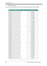
Page 86: ... 6 P1 S1 REG06 7 P1 S1 REG07 8 P1 S1 REG08 9 P1 S1 REG09 10 P1 S1 REG10 11 P1 S1 REG11 12 P1 S1 REG12 13 S2 P1 S2 REG00 14 P1 S2 REG01 15 P1 S2 REG02 16 P1 S2 REG03 17 P1 S2 REG04 18 P1 S2 REG05 19 P1 S2 REG06 20 P1 S2 REG07 21 P1 S2 REG08 22 P1 S2 REG09 23 P1 S2 REG10 24 P1 S2 REG11 25 P1 S2 REG12 26 S3 P1 S3 REG00 27 P1 S3 REG01 28 P1 S3 REG02 29 P1 S3 REG03 30 P1 S3 REG04 31 P1 S3 REG05 32 P1 S...

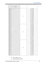
Page 87: ...G12 247 S2 L1 S2 REG00 248 L1 S2 REG01 249 L1 S2 REG02 250 L1 S2 REG03 251 L1 S2 REG04 252 L1 S2 REG05 253 L1 S2 REG06 254 L1 S2 REG07 255 L1 S2 REG08 256 L1 S2 REG09 257 L1 S2 REG10 258 L1 S2 REG11 259 L1 S2 REG12 260 S3 L1 S3 REG00 261 L1 S3 REG01 262 L1 S3 REG02 263 L1 S3 REG03 264 L1 S3 REG04 265 L1 S3 REG05 266 L1 S3 REG06 267 L1 S3 REG07 268 L1 S3 REG08 269 L1 S3 REG09 270 L1 S3 REG10 271 L1...

Page 88: ...P_42 JP_41 Register REG06 bit 7 6 5 4 3 2 1 0 JP_56 JP_55 JP_54 JP_53 JP_52 JP_51 JP_50 JP_49 Register REG07 bit 7 6 5 4 3 2 1 0 JP_64 JP_63 JP_62 JP_61 JP_60 JP_59 JP_58 JP_57 Register REG08 bit 7 6 5 4 3 2 1 0 JP_72 JP_71 JP_70 JP_69 JP_68 JP_67 JP_66 JP_65 Register REG09 bit 7 6 5 4 3 2 1 0 JP_80 JP_79 JP_78 JP_77 JP_76 JP_75 JP_74 JP_73 Register REG10 bit 7 6 5 4 3 2 1 0 JP_88 JP_87 JP_86 JP_8...

Page 89: ... 7 R1 S1 REG07 8 R1 S1 REG08 9 R1 S1 REG09 10 R1 S1 REG10 11 R1 S1 REG11 12 R1 S1 REG12 13 S2 R1 S2 REG00 14 R1 S2 REG01 15 R1 S2 REG02 16 R1 S2 REG03 17 R1 S2 REG04 18 R1 S2 REG05 19 R1 S2 REG06 20 R1 S2 REG07 21 R1 S2 REG08 22 R1 S2 REG09 23 R1 S2 REG10 24 R1 S2 REG11 25 R1 S2 REG12 26 S3 R1 S3 REG00 27 R1 S3 REG01 28 R1 S3 REG02 29 R1 S3 REG03 30 R1 S3 REG04 31 R1 S3 REG05 32 R1 S3 REG06 33 R1 ...

Page 90: ... JP_42 JP_41 Rejestr REG06 bit 7 6 5 4 3 2 1 0 JP_56 JP_55 JP_54 JP_53 JP_52 JP_51 JP_50 JP_49 Rejestr REG07 bit 7 6 5 4 3 2 1 0 JP_64 JP_63 JP_62 JP_61 JP_60 JP_59 JP_58 JP_57 Rejestr REG08 bit 7 6 5 4 3 2 1 0 JP_72 JP_71 JP_70 JP_69 JP_68 JP_67 JP_66 JP_65 Rejestr REG09 bit 7 6 5 4 3 2 1 0 JP_80 JP_79 JP_78 JP_77 JP_76 JP_75 JP_74 JP_73 Rejestr REG10 bit 7 6 5 4 3 2 1 0 JP_88 JP_87 JP_86 JP_85 J...

Page 91: ...nsors test 1 98 1188 99 UnitsConfig Serial L Factory bay unit number the serial number lower byte 1189 UnitsConfig Serial H Factory bay unit number the serial number higher byte 1190 UnitsConfig Control Bay unit network status 1191 UnitsConfig Status Bay unit working status 1192 UnitsConfig SensorState Bay unit optical sensors status 1193 UnitsConfig SensorSet Bay unit optical sensors activation s...

Page 92: ...ptical sensors signaling 3 RAS1 Signaling of remote tripping in zone S1 2 AS3 Signaling of tripping in zone S3 1 AS2 Signaling of tripping in zone S2 0 AS1 Signaling of tripping in zone S1 Register UnitsConfig SensorState bit 7 6 5 4 3 2 1 0 P4 P3 P2 P1 Bit number Mnemonics Description 7 4 Reserved 3 0 P 4 1 Logical state of optical sensor C 4 1 Register UnitsConfig SensorSet bit 7 6 5 4 3 2 1 0 P...

Page 93: ...x tripping in zone Z2 1 1 Optical sensor Cx tripping in zone Z3 Register UnitsConfig FlashTestStatus MxA MxB Optical sensors test status 0 0 test has not been performed 0 1 test performed but the sensor not checked off in the bay unit 1 0 test performed but the sensor damaged 1 1 test performed and the sensor operational bit 7 6 5 4 3 2 1 0 C4A C4B C3A C3B C2A C2B C1A C1B ...

Page 94: ...g Serial L Factory executive unit number the serial number lower byte 1249 UnitsConfig Serial H Factory executive unit number the serial number higher byte 1250 UnitsConfig Control Executive unit network status 1251 UnitsConfig Status Executive unit working status 1252 Reserved 1253 Reserved 1254 Reserved 1255 Reserved 1256 Reserved 1257 Reserved 1258 Reserved 1259 Reserved Rejestr UnitsConfig Con...

Page 95: ...p should cover the control of activation of optic detectors activation of voltage elements external and internal signaling circuits activation of all tripping circuits by simulating an arc fault At least once a year apart from the functional check the operate time of the protection should be checked The producer provides services repairs and periodic tests of the arc fault protection sys tems 15 2...

Page 96: ...f the class 1 The device delivered by the producer should be unpacked carefully not with use of too much strength and not adequate tools After unpacking it should be visually checked if the device has no external damage The device should be stored in a dry and clean place The temperature of the storage is in the range from 25 C up to 70 C Relative humidity should be in such a range that condensati...

Page 97: ...ranty 19 Ordering The order should include the amount of the central units ZŁ 4A JC the amount of the bay units ZŁ 4A JP the amount of the bay units ZŁ 4A JW the amount of the power supplies the amount of the optical detectors with specified length the maximum length of the fiber reserve is 1 meter the type of the switchgear where the protection will be installed name and contact details of the pe...

Reviews: