EK-Pak Owner and Installation Manual
EK-Pak Owner & Installation Manual First Edition December 2002
20
WARNING
: The pipe heaters located on the heating module will not protect any hot or cold
water piping. Properly protect and insulate these pipes from freezing.
NOTICE:
If the EK-Pak Heating module may be exposed to freezing temperatures, such as a
vacation home shut down for the winter or the temperatures drop below 35
°
F (2
°
C) with wind
chill, then anti-freeze should be added to the heating module water. If the system was
installed for hot water only, then the domestic piping and the heating module must be drained.
When a home is winterized by draining all domestic water piping, then the EK-Pak Heating
module must be protected. When draining the domestic water piping system, be sure to drain
the domestic side of the plate heat exchanger. If the hydronic system will not be drained, then
add enough anti-freeze to protect the entire hydronic system including the heating module,
piping, radiation, circulators, etc. Propylene Glycol in water will provide the following freeze
protection: 30% down to +8
o
F, 40% to -8
o
F, 50% to -27
o
F. Energy Kinetics recommends
using 30% anti-freeze to obtain the best heating module performance. Use over 30% anti-
freeze only if lower temperature freeze protection is mandatory.
Combustion Air and Venting:
Follow all local codes, or in the
absence of local codes, follow the codes for installation of Gas
Burning Appliances; National Fuel Gas Code ANSI Z221.33.
Combustion Air Supply:
The EK-Pak is a direct vent (Sealed Combustion) system. All the combustion air supplied
to the unit is supplied from outside of the building.
Suitable piping such as galvanized single wall vent pipe, PVC, corrugated stainless steel
pipe and Category III stainless steel vent pipe may be used.
Use 3” piping for the air intake with maximum length of 20 feet and 5 elbows. Use 4” piping
and 5 elbows for runs up to 40 feet.
Exhaust Venting:
WARNING:
The EK-Pak must be connected to a 4” Category III gas vent pipe in order to
direct any dangerous exhaust byproducts to the outdoors.
WARNING:
Do not common vent this appliance with any other vented appliance.
NOTICE:
The following instructions apply to Energy Kinetics supplied Z-Vent III product (See
replacement parts section for Energy Kinetics part numbers). When installing vent pipe from
another manufacturer, ensure that the manufacturers instructions are followed. This is a
Category III appliance and must be vented accordingly.
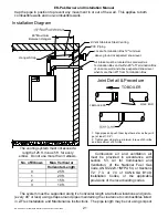
Passage through a combustible wall requires the use of the Wall Thimble. If the wall is
non-combustible the pipe may be mortared in directly. Observe these rules and/or local
building codes. Cut a six-inch diameter hole in the wall and slide each half of the thimble in
from each side of the wall. Fasten the 10-inch by 10-inch square flanges to each side of the
wall and caulk around the outside edge of the plates as necessary. The Thimble is adjustable
for different wall thickness. The vent pipe must be sealed at the wall thimble as per code
regarding continuous vapor barrier.
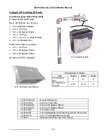
Assemble the system following the Installation Diagram and the Joint Detail & Procedure
below. A gear clamp or locking strap must be installed on the pipe at the inside of the wall to

