SERIES 8500-2400 PX BOOSTER PUMPS
Energy Recovery, Inc.
12
ERI Document Number 80020-01-2
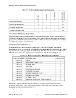
Table 7-3 - Recommended Tools and Materials
Pump Model
Tool
Application
all 9/16-inch
Wrench
Bolts between Inlet Housing
and Bell Housing
all 3/4-inch
Wrench
Bolts between Bell Housing
and Motor
8500-pumps 3/16-inch
Allen/Hex Wrench
Coupling
1250- and 2400-pumps
1/4-inch Allen/Hex Wrench
Coupling
all
3/32-inch Allen/Hex Wrench
Seal Set Screws
all
Anti-Seize Compound
All Threads
all
Water Soluble Lubricant
O-Rings
The following procedure provides instructions for removing an old seal and inserting a new
one.
7.3.1 Remove the Old Mechanical Seal
1. Verify system is de-energized and un-pressurized.
2. Disconnect the flexible coupling connections from the inlet and outlet of the PX Booster
Pump and allow water to drain from system.
3. Unbolt the motor base from the floor.
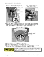
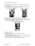
4. Stand the PX Booster Pump on the motor in a vertical orientation as shown in Figure 7-2.
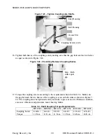
5. Partially loosen (1-3 turns) the eight (8) shaft coupling screws inside the bell housing.
There is an access slot for these screws at the side of the bell housing. See Figure 7-3.
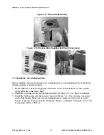
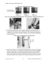
6. Remove the four bolts that hold the inlet housing to the bell housing with a 9/16” wrench
as shown in Figure 7-4.
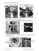
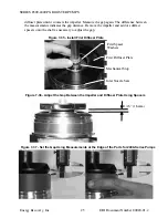
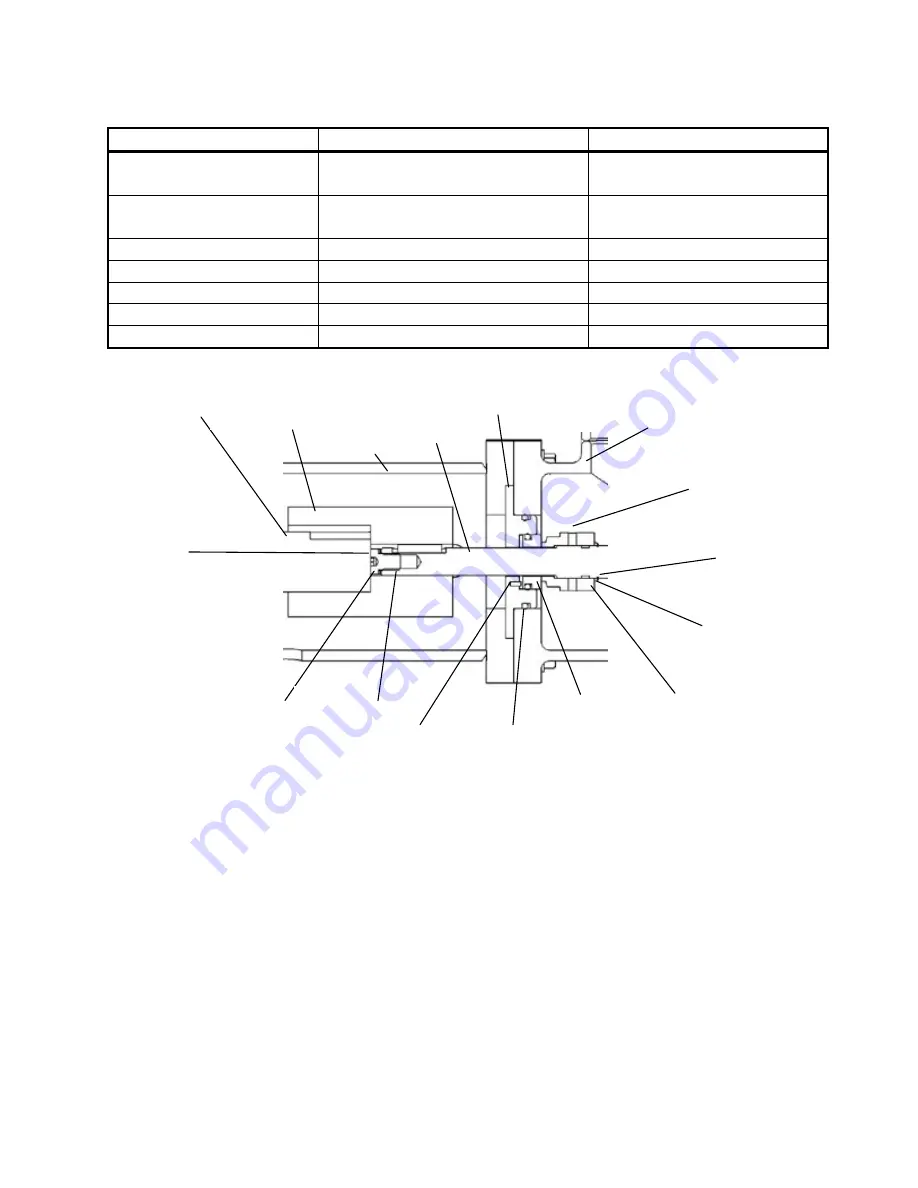
Figure 7-1 - Section View of Shaft and Seal Components
Motor
Shaft
Coupling
Bell
Housing
Pump
Shaft
Seal
Plate
Jack
Screw
Stationary
Seal
Primary
Seal
Window to
check
Compression
shafts in
contact
Inlet
Housing
Pin
O-Ring
Spacer
10122-01
Retaining
Ring
Shim
Spacer(s)
10055-01


