background image

 
SERIES 8500-2400 PX BOOSTER PUMPS 

Energy Recovery, Inc. 

31 

ERI Document Number 80020-01-2


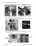
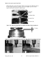
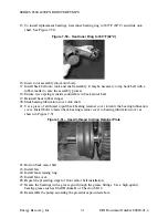
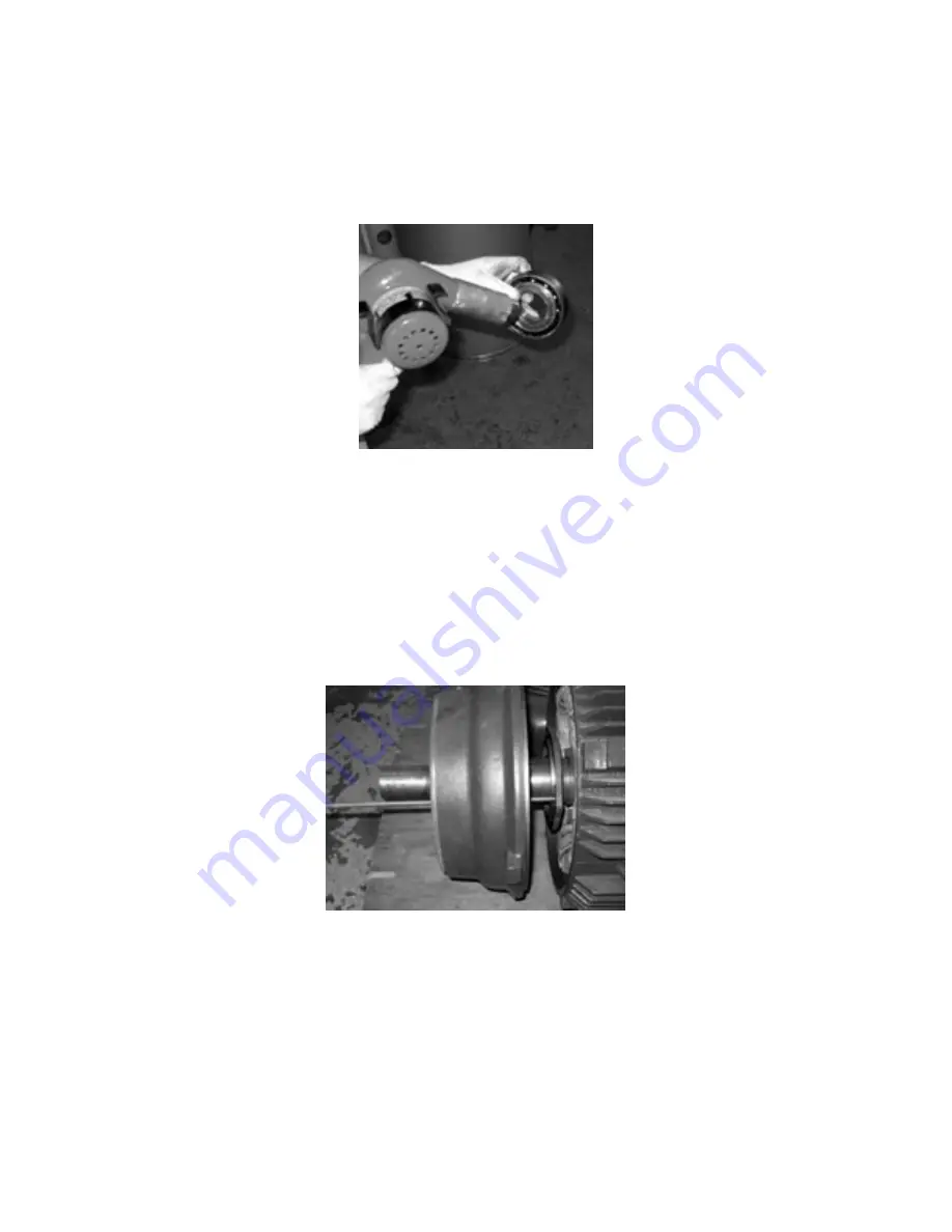
15. To install replacement bearings, heat inner bearing ring to 180°F (82°C) and slide onto 

shaft. See Figure 7-50.  

Figure 7-50 – Heat Inner Ring to 180°F (82°C) 


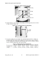
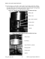
16. Insert rotor assembly into motor body. 
17. Install back bell onto rotor and shaft assembly. It maybe necessary to tap back bell with a 

rubber mallet to ease the assembly process.  

18. Ensure wave spring is inside counterbore in back motor bell. 
19. Reinstall back rubber slinger. 
20. Slide bearing lubrication cover onto shaft. 
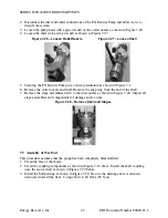
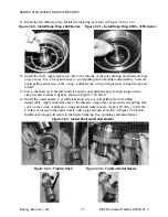
21. Use a piece of all thread to pull back bearing retainer cover towards the bearing lubrication 

cover. Install bolts to fasten back bearing retainer cover to bearing lubrication cover as 
shown in Figure 7-51. 

Figure 7-51 – Use All-thread to Align Retainer Plate 


22. Bolt on back motor bell. 
23. Install  fan. 
24. Install fan retaining ring. 
25. Install fan cover. 
26. Repeat the preceding steps for front motor bell installation. 
27. Grease the bearings with a grease gun through the grease fittings. Use a high-quality 

bearing grease such as Shell Dolium R or Chevron SR1 2. 

28. Reassemble the pump according the procedures provided above.  

Summary of Contents for 2400 Series

Page 1: ...NC 441144 INSTALLATION OPERATION MAINTENANCE MANUAL Series 8500 2400 PX Booster Pumps Energy Recovery Inc 1908 Doolittle Drive San Leandro CA 94577 USA Tel 1 510 483 7370 Fax 1 510 483 7371 www energy recovery com sales energy recovery com Energy Recovery Inc 2001 2005 ...

Page 2: ...AUTIONS AND CONDITIONS 8 6 1 4 PHYSICAL CHARACTERISTICS 8 6 1 5 UTILITY REQUIREMENTS 9 6 1 6 SPARE PARTS 9 6 2 STARTUP PROCEDURE 9 6 3 MAINTENANCE AND STARTUP LOG 10 7 0 MAINTENANCE INSTRUCTIONS 10 7 1 GENERAL 10 7 2 LUBRICATE BOOSTER PUMP MOTOR 11 7 3 MECHANICAL SEAL MAINTENANCE 11 7 3 1 REMOVE THE OLD MECHANICAL SEAL 12 7 3 2 INSTALL THE NEW MECHANICAL SEAL 15 7 4 DISASSEMBLY OF WET END 21 7 5 A...

Page 3: ...ce are available Further information about PX Booster Pumps or other Energy Recovery Inc products or service can be found by contacting Energy Recovery Inc at Energy Recovery Inc 1908 Doolittle Drive San Leandro CA 94577 USA Tel 1 510 483 7370 Fax 1 510 483 7371 www energy recovery com sales energy recovery com 2 0 MATERIALS OF CONSTRUCTION AND QUALITY ERI s commitment to quality starts with the f...

Page 4: ...ould be inspected immediately upon arrival and any irregularities due to shipment should be reported to the carrier PX Booster Pump units are securely packed with plugs in the fittings to protect the unit from damage during transportation Care must be taken during unpacking and handling to avoid damage to the PX Booster Pump 4 0 PRINCIPLE OF OPERATION The PX Booster Pump is designed to be used in ...

Page 5: ...in the PX unit s the membranes and the associated piping The PX Booster Pump is specially designed to handle high operating pressures while consuming minimal energy to provide a small boost to the high pressure flow The PX Booster Pump also serves to drive the flow of the high pressure stream through the PX unit s G and D Fully pressurized seawater then merges with the main seawater to the SWRO sy...

Page 6: ...face locations and minimum maintenance envelope requirements 1 Place the PX Booster Pump in an appropriate location and mount the motor securely making sure that the base of the unit is permanently supported 2 Connect the inlet and outlet of the pump to the appropriate points Proper piping piping support and motor mounts must be implemented to minimize external stresses on all piping fittings Flex...

Page 7: ...g service life Failure to observe these conditions and precautions can result in violation of the warranty damage to the equipment and or harm to personnel Disconnect electrical supply before installing and or servicing the pump Failure to do so can cause serious injury or death to personnel Strictly observe all applicable electrical codes and regulations governing the installation and wiring of e...

Page 8: ...induce stress on the pump or motor Ensure that all flexible connections are secure and tight before operating pump Under no circumstances shall the inlet pressure or outlet pressure exceed 1 200 psig 83 bar Ensure sufficient feed water supply The PX Booster Pump should be thoroughly purged of air before startup Operating the PX Booster Pump with feed pressures less than 15 psi may result in damage...

Page 9: ...s provide impellers stage assemblies and O rings Table 6 4 Recommended Spare Parts DESCRIPTION QTY O RING KIT PART NUMBER REBUILD KIT PART NUMBER MECHANICAL SEAL KIT HP 8503 1 20005 02 20005 01 20004 01 HP 8504 1 20006 02 20006 01 20004 01 HP 1253 1 20007 02 20007 01 20004 01 HP 1254 1 20008 02 20008 01 20004 01 HP 2402 1 20009 02 20009 01 20004 01 HP 2403 1 20010 02 20010 01 20004 01 Includes Imp...

Page 10: ... support any claims Include pump serial number with all submittals Submittal of the maintenance and startup log to ERI within 24 hours of startup is a condition of obtaining PX Booster Pump warranty coverage The data must be recorded daily and maintained during the life of the warranty in order to support any claims 7 0 MAINTENANCE INSTRUCTIONS 7 1 General The table below details the specific reco...

Page 11: ... used to seal the rotating shaft This seal will require replacement approximately every 12 18 months An indication that maintenance is required will be a leak or drip from the rear of the pump into the bell housing Mechanical seal kits are available from ERI The kit includes the components listed in Table 7 2 and illustrated in Figure 7 1 Table 7 2 Mechanical Seal Kit ERI Part Number 20004 01 PART...

Page 12: ...e energized and un pressurized 2 Disconnect the flexible coupling connections from the inlet and outlet of the PX Booster Pump and allow water to drain from system 3 Unbolt the motor base from the floor 4 Stand the PX Booster Pump on the motor in a vertical orientation as shown in Figure 7 2 5 Partially loosen 1 3 turns the eight 8 shaft coupling screws inside the bell housing There is an access s...

Page 13: ... gap between the seal plate and the inlet 9 The mechanical seal includes the primary seal and the stationary or mating plate as shown in Figure 7 6 Extract the stationary plate from the seal plate by pushing through the seal plate with a rod as shown in Figure 7 7 Remove stationary plate from the seal plate Bell Housing Coupling Screws 4x2 Figure 7 3 Loosen Coupling Screws Access Slot Figure 7 2 P...

Page 14: ...2 Remove the bell housing from the motor as shown in Figure 7 9 13 Remove the coupling from the motor shaft Disassemble the coupling as shown in Figure 7 10 Clean the coupling and the shaft keys to remove any salt deposits or debris Mechanical seal set screw 4ea 3 32 inch hex Figure 7 8 Loosen Set Screws Primary Seal Stationary Plate Seal Plate Figure 7 6 Mechanical Seal Components Stationary Plat...

Page 15: ...de of the coupling Apply antiseize to the motor shaft 2 Install the coupling onto the motor shaft as shown in Figure 7 11 Use plenty of antiseize 3 Install the bell housing onto the motor as shown in Figure 7 11 Use anti seize compound on the bolt threads Make sure that the drainage hole is oriented so that it will be on the bottom of the bell housing when the PX Booster Pump is reinstalled Torque...

Page 16: ...n pin into the seal plate as shown in Figure 7 14 Once inserted the pin should not protrude more than 1 16 inch 1 6 mm Assure that there is no debris inside the seal plate that would prevent the stationary seal from fully seating 6 Lubricate the O ring of the new stationary seal with a water based lubricant such as glycerin or soap Insert the new stationary seal into the seal plate Be sure to line...

Page 17: ...haft Seal and Seal Plate Install into Inlet Housing 8 Align the shaft key with the slot in the coupling and install the pump onto the bell housing as shown in Figure 7 17 Figure 7 17 Install Pump into Bell Housing Figure 7 14 Insert Anti Rotation Pin Figure 7 15 Stationary Seal Line up Pin with Groove Groove Pin Antiseize Key Align shaft key with slot in coupling Finger tight ...

Page 18: ...ward force on the pump shaft while looking into the inlet housing as shown in Figure 7 19 Figure 7 19 Install Pump onto Bell Housing 11 Inspect the mechanical seal inside the inlet housing Check the compression of the mechanical seal by looking into the circular window as shown in Figure 7 20 If seal is not correctly compressed remove the pump and install a fender washer into the shaft coupling or...

Page 19: ...all the four 4 bolts between the pump to finger tight Figure 7 22 Install Pump into Bell Housing 15 With the pump and motor shafts in contact tighten the eight 8 coupling screw as shown in Figure 7 23 NOTE THE PUMP AND MOTOR SHAFT MUST BE IN CONTACT Figure 7 21 Add or Remove Fender Washer s or Shim Spacer s to Change Seal Compression Figure 7 20 Check Seal Compression Circular Window to Check Comp...

Page 20: ...n on both sides as shown in Figure 7 24 The coupling must be tightened evenly and fully to prevent an out of balance condition excessive vibration and premature motor bearing failure Table 7 4 Shaft Coupling Torque Requirements HP 8503 HP 8504 HP 1253 HP 1254 HP 2402 HP 2403 Coupling Screw Torque 8 ft lb 11 N m 8 ft lb 11 N m 8 ft lb 11 N m 8 ft lb 11 N m 12 ft lb 16 N m 12 ft lb 16 N m Figure 7 2...

Page 21: ...re with the bowls premature failure of the pump may occur A small amount of rubbing during an initial break in period is acceptable 20 After the pump is reassembled and reinstalled make sure that water is fully flowing through the unit before starting THE PUMP CANNOT BE RUN DRY FOR EVEN A FEW SECONDS Damage will occur in seconds if the pump runs with insufficient feed flow 7 4 Disassembly of Wet E...

Page 22: ...ng from the end of the shaft 7 Remove the stage assemblies down to the inlet nozzle as shown in Figure 7 28 Inspect all stage assemblies and components for damage and or wear 7 5 Assembly of Wet End This procedure assumes that the pump has been completely disassembled 1 Clean the face of the motor 2 Clean the coupling components as shown in Figure 7 14 above Install the shaft coupling onto the mot...

Page 23: ...haft and motor shaft are in contact Figure 7 31 Insert Shaft Assembly into Bell Housing and Coupling 7 Check the compression of the mechanical seal while applying downward force on the shaft by looking into the circular window as shown in Figure 7 32 If seal is not correctly compressed remove the pump and install a fender washer into the shaft coupling or a shim spacer onto the shaft as shown in F...

Page 24: ...wear ring of the diffuser plate to 1 16 1 6mm 1 32 0 8mm as shown in Figure 7 35 Remove the impeller and add or subtract spacers onto the shaft as necessary to adjust the gap For 2400 Series PX Booster Pump models the gap between the impeller and the wear ring cannot be directly viewed In this case measure the distance between any two features on the diffuser plate and the impeller as shown in Fig...

Page 25: ...he gap distance Remove the impeller and add or subtract spacers onto the shaft as necessary to adjust the gap Inlet Nozzle Seat First Diffuser Plate Mechanical Stop First Spacer Washers Figure 7 35 Install First Diffuser Plate 1 16 1 6mm Figure 7 36 Adjust the Gap Between the Impeller and Diffuser Plate Using Spacers Figure 7 37 Set the Gap Using Measurements at the Edge of the Parts for 2400 Seri...

Page 26: ...eller and diffuser plate make up a complete stage assembly as shown in Figure 7 38 Stack in the order shown in Figure 7 38 or 7 39 until the pump is complete Diffuser bowl Spacer washer optional Bearing journal Thrust washer Impeller Diffuser plate Figure 7 38 Complete Stage Assembly for 8500 and 1250 Series Pumps Figure 7 39 Complete Stage Assembly for 2400 Series Pumps Bowl Sleeve Spacer Washer ...

Page 27: ... then apply enough torque with a strap wrench to make it tight as shown in Figure 7 43 below 14 Install the outlet nozzle Use sufficient anti seize to avoid galling and to facilitate disassembly Apply anti seize only to the threads wipe away excess and avoid getting anti seize on the o ring Lubricate o ring and install outlet nozzle Apply 150 ft lb 20 ft lbs 0 ft lbs of torque to the outlet nozzle...

Page 28: ... long service life if properly and regularly lubricated The motor manual included in Section 12 0 provides guidance for proper motor maintenance In case of bearing failure ERI supplies the replacement bearings listed in Table 7 5 Table 7 5 Replacement Motor Bearings BOOSTER PUMP MODEL BACK LOAD BEARING FRONT THRUST BEARING HP 8503 10228 01 10227 01 HP 8504 10228 02 10227 03 HP 1253 GE 10228 02 102...

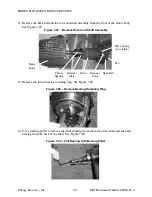
Page 29: ...g to steps 1 though 6 of the Mechanical Seal Change procedure provided in Section 7 3 4 Remove the bell housing 5 Remove the coupling from the motor shaft Disassemble the coupling as shown in Figure 7 10 Clean the coupling and the shaft keys to remove any salt deposits or debris 6 Remove the fan cover from the motor 7 Remove fan snap ring 8 Remove the fan 9 Remove the rubber slingers x2 10 Remove ...

Page 30: ...otor and Shaft Assembly 13 Remove the thrust bearing retaining ring See Figure 7 48 Figure 7 48 Remove Bearing Retaining Ring 14 Use a bearing puller to remove the thrust bearing from the front of the shaft and the back bearing from the back of the shaft See Figure 7 49 Figure 7 49 Pull Bearing with Bearing Puller Motor Body Thrust Bearing Retainer Plate Rotor Retainer Plate Back Bell Fan Wave Spr...

Page 31: ...all back rubber slinger 20 Slide bearing lubrication cover onto shaft 21 Use a piece of all thread to pull back bearing retainer cover towards the bearing lubrication cover Install bolts to fasten back bearing retainer cover to bearing lubrication cover as shown in Figure 7 51 Figure 7 51 Use All thread to Align Retainer Plate 22 Bolt on back motor bell 23 Install fan 24 Install fan retaining ring...

Page 32: ...ecking for continuity and solid contact can prevent hours of wasted effort 3 Always inspect and test equipment or apparatus for probable cause of malfunction before performing replacement When using the troubleshooting guide read all the probable causes before taking any action Use good common sense and then use the probable cause that most likely fits the given situation Table 8 1 Troubleshooting...

Page 33: ...n and out freely Make sure that the switch is not loose on the shaft Inspect contacts and connections on the stationary switch Replace switch if the contacts are burned or pitted C Motor runs but dies down Voltage drop If voltage is less than 10 of the motor s rating contact power company or check if some other equipment is taking power away from the motor Load increased Verify the load has not ch...

Page 34: ...nameplate Ambient temperature too high Verify that the motor is getting enough air for proper cooling Most motors are designed to run in an ambient temperature of less than 40 C Note A properly operating motor may be hot to the touch Protector may be defective Replace the motor s protector with a new one of the same rating Winding shorted or grounded Inspect stator for defects or loose or cut wire...

Page 35: ...uired Damaged motor Replace motor H Leak Leaky connection Check couplings Mechanical seal failure Inspect and or replace mechanical seal Damaged o ring Inspect o rings I Excessive noise Excessive flow rate Lower flow rate or apply backpressure to pump Insufficient feed water Check feed pressure and inspect wet end assembly Motor bearing failure Check motor bearings and or replace motor ...

Page 36: ...ms Initial data must be submitted within 24 hours of startup Fax 1 510 483 7371 Attn Warranty Administration Department Model of PX Booster Pump _____________________________________________________ Serial Number s ______________________________________________________________ Units please circle one psi gpm bar m3 hr Date Total Hours HP Inlet Pressure HP Outlet Pressure HP Flow Motor Bearings Lub...

Page 37: ...commissioning is not a requirement some customers might feel more comfortable with the offered service Rates can be quoted upon request Should a problem develop with any ERI product our Technical Services group is prepared to handle customers concerns whether the location is domestic or overseas Service rates are available upon request Energy Recovery Inc 1908 Doolittle Drive San Leandro CA 94577 ...

Page 38: ...irect measurement using an ultrasonic high pressure flow meter or similar instrument Maximum operating pressure must not exceed 1 200 psi Client Responsibilities Initial piping system flushing Before a PX Booster Pump is installed client must insure that all piping is cleaned and flushed with water in a way that all construction debris is removed from the system Filtration Water flowing to the PX ...

Page 39: ...s and photos Add seal compression and shim instructions 11 21 03 RLS 1 Update spare parts numbers seal change procedure add RMA form update drawings 5 13 04 RLS 2 Trademarks revised pump curves added motor bearing service added warranty 1 24 05 RLS 12 0 DRAWINGS AND DATA 1 PX Booster Pump Assembly Drawings Overall Dimensions and Labeling Diagrams Shipping Configuration Drawings 2 PX Booster Pump C...

Page 40: ...A B C D 1 2 3 4 5 6 7 8 8 7 6 5 4 3 2 1 E F E F DRAWN CHECKED ENG APPR TITLE SIZE DWG NO 05 12 2003 RAC TLS 05 28 2003 RLS THIRD ANGLE PROJECTION ASSY PUMP PROPRIETARY AND CONFIDENTIAL IS THE SOLE PROPERTY OF ENERGY RECOVERY INC ANY REPRODUCTION IN PART OR AS A WHOLE WITHOUT THE WRITTEN PERMISSION OF C 2004 ENERGY RECOVERY INC ENERGY RECOVERY INC BOOSTER HP 8503 05 28 2003 ENERGY RECOVERY INC IS P...

Page 41: ...0VAC AMPS 6 2 1 D C B A A B C D 1 2 3 4 5 6 7 8 8 7 6 5 4 3 2 1 E F E F DRAWN CHECKED ENG APPR TITLE SIZE DWG NO 05 12 2003 RAC TLS 05 28 2003 RLS THIRD ANGLE PROJECTION ASSY PUMP PROPRIETARY AND CONFIDENTIAL PRODUCT INCH SCALE 1 1 DRAWING STATUS 1 50000 1908 Doolittle Drive San Leandro CA 94577 Ph 510 483 7370 Fax 510 483 7371 www energy recovery com WEIGHT SHEET 2 OF 3 REV C THE INFORMATION CONT...

Page 42: ...70 Fax 510 483 7371 www energy recovery com WEIGHT SHEET 3 OF 3 REV C THE INFORMATION CONTAINED IN THIS DRAWING IS THE SOLE PROPERTY OF ENERGY RECOVERY INC ANY REPRODUCTION IN PART OR AS A WHOLE WITHOUT THE WRITTEN PERMISSION OF ENERGY RECOVERY INC IS PROHIBITED 05 28 2003 BOOSTER HP 8503 ENERGY RECOVERY INC 2004 ENERGY RECOVERY INC C Wednesday March 02 2005 7 38 38 PM C Engineering Documents Prod...

Page 43: ...LG KEY 316 SS 26 1 10117 01 DOWEL 3 32 DIA X 1 4 LG ACETAL 27 1 10122 01 SPACER SEAL PVC 28 1 51053 01 ASSY SHAFT ALL SPLINE 8504 PUMP AL6XN 29 1 51002 NOZZLE OUTLET BOOSTER PUMP AL6XN 30 4 10138 02 BOWL DIFFUSER 080 SERIES NORYL 2 1 50001 D C B A A B C D 1 2 3 4 5 6 7 8 8 7 6 5 4 3 2 1 E F E F DRAWN CHECKED ENG APPR TITLE SIZE DWG NO 05 12 2003 RAC TLS 05 28 2003 RLS THIRD ANGLE PROJECTION ASSY P...

Page 44: ...FORMATION CONTAINED IN THIS DRAWING IS THE SOLE PROPERTY OF ENERGY RECOVERY INC ANY REPRODUCTION IN PART OR AS A WHOLE WITHOUT THE WRITTEN PERMISSION OF ENERGY RECOVERY INC IS PROHIBITED 05 28 2003 BOOSTER HP 8504 ENERGY RECOVERY INC 2004 ENERGY RECOVERY INC C Wednesday March 02 2005 7 38 58 PM C Engineering Documents Production Drawings 50000 booster pump product assemblies 50001 REFERENCE SCALE ...

Page 45: ...DWG NO 05 12 2003 RAC TLS 05 28 2003 RLS THIRD ANGLE PROJECTION ASSY PUMP PROPRIETARY AND CONFIDENTIAL PRODUCT INCH SCALE 1 8 DRAWING STATUS 1 50001 1908 Doolittle Drive San Leandro CA 94577 Ph 510 483 7370 Fax 510 483 7371 www energy recovery com WEIGHT SHEET 3 OF 3 REV C THE INFORMATION CONTAINED IN THIS DRAWING IS THE SOLE PROPERTY OF ENERGY RECOVERY INC ANY REPRODUCTION IN PART OR AS A WHOLE W...

Page 46: ...EAL PVC 28 1 51051 01 ASSY SHAFT ALL SPLINE 1253 PUMP AL6XN 29 1 51002 NOZZLE OUTLET BOOSTER PUMP AL6XN 30 3 10139 01 BOWL DIFFUSER 120 SERIES NORYL 2 1 50002 D C B A A B C D 1 2 3 4 5 6 7 8 8 7 6 5 4 3 2 1 E F E F DRAWN CHECKED ENG APPR TITLE SIZE DWG NO 05 12 2003 RAC TLS 05 28 2003 RLS THIRD ANGLE PROJECTION ASSY PUMP PROPRIETARY AND CONFIDENTIAL IS THE SOLE PROPERTY OF ENERGY RECOVERY INC ANY ...

Page 47: ... E F E F DRAWN CHECKED ENG APPR TITLE SIZE DWG NO 05 12 2003 RAC TLS 05 28 2003 RLS THIRD ANGLE PROJECTION ASSY PUMP PROPRIETARY AND CONFIDENTIAL PRODUCT INCH SCALE 1 4 5 DRAWING STATUS 1 50002 1908 Doolittle Drive San Leandro CA 94577 Ph 510 483 7370 Fax 510 483 7371 www energy recovery com WEIGHT SHEET 2 OF 3 REV C THE INFORMATION CONTAINED IN THIS DRAWING IS THE SOLE PROPERTY OF ENERGY RECOVERY...

Page 48: ...LS THIRD ANGLE PROJECTION ASSY PUMP PROPRIETARY AND CONFIDENTIAL PRODUCT INCH SCALE 1 8 DRAWING STATUS 1 50002 1908 Doolittle Drive San Leandro CA 94577 Ph 510 483 7370 Fax 510 483 7371 www energy recovery com WEIGHT SHEET 3 OF 3 REV C THE INFORMATION CONTAINED IN THIS DRAWING IS THE SOLE PROPERTY OF ENERGY RECOVERY INC ANY REPRODUCTION IN PART OR AS A WHOLE WITHOUT THE WRITTEN PERMISSION OF ENERG...

Page 49: ...ESCRIPTION MATERIAL 1 1 51039 01 MOTOR 15 H P 254TC 2 1 1 51000 01 HOUSING BELL BOOSTER PUMP ALUM 3 1 1 51008 01 PLATE SEAL AL6XN 4 1 1 51005 01 INLET BOOSTER PUMP AL6XN 5 1 1 51041 01 3 16 SQ X 1 LG KEY 316 SS 6 1 1 10123 01 SEAL SHAFT MECHANICAL 316SS 7 1 1 10061 01 RING RETAINING C 276 8 1 1 10066 01 RING RETAINING C 276 9 1 1 51030 01 COUPLING STEPPED 1 5 8 X 5 8 TITANIUM 10 4 4 10068 01 WASHE...

Page 50: ... THIRD ANGLE PROJECTION ASSY PUMP PROPRIETARY AND CONFIDENTIAL PRODUCT INCH SCALE 1 5 25 DRAWING STATUS 1 50003 1908 Doolittle Drive San Leandro CA 94577 Ph 510 483 7370 Fax 510 483 7371 www energy recovery com WEIGHT SHEET 2 OF 3 REV C THE INFORMATION CONTAINED IN THIS DRAWING IS THE SOLE PROPERTY OF ENERGY RECOVERY INC ANY REPRODUCTION IN PART OR AS A WHOLE WITHOUT THE WRITTEN PERMISSION OF ENER...

Page 51: ...THE WRITTEN PERMISSION OF ENERGY RECOVERY INC IS PROHIBITED 05 28 2003 BOOSTER HP 1254 ENERGY RECOVERY INC 2004 ENERGY RECOVERY INC C Wednesday March 02 2005 7 39 39 PM C Engineering Documents Production Drawings 50000 booster pump product assemblies 50003 REFERENCE SCALE SEE SHEET 1 FOR REVISIONS 19 3 4 56 SHIPPING WEIGHT 380 LBS 172 5 Kgs COVER NOT SHOWN IF REQUIRED REMOVE ELECTRICAL JUNCTION BO...

Page 52: ... DOWEL 3 32 DIA X 1 4 LG ACETAL 30 1 1 10122 01 SPACER SEAL PVC 31 1 51037 01 MOTOR 15 H P 254T BOLT ON C FLANGE 32 1 51055 01 ASSY SHAFT ALL SPLINE 2402 PUMP AL6XN 33 1 51055 01 ASSY SHAFT ALL SPLINE 2402 PUMP AL6XN 34 1 51002 NOZZLE OUTLET BOOSTER PUMP AL6XN 35 1 51001 NOZZLE OUTLET BOOSTER PUMP AL6XN 2 1 50004 D C B A A B C D 1 2 3 4 5 6 7 8 8 7 6 5 4 3 2 1 E F E F DRAWN CHECKED ENG APPR TITLE ...

Page 53: ...PROPERTY OF ENERGY RECOVERY INC ANY REPRODUCTION IN PART OR AS A WHOLE WITHOUT THE WRITTEN PERMISSION OF ENERGY RECOVERY INC IS PROHIBITED 05 28 2003 BOOSTER HP 2402 ENERGY RECOVERY INC 2004 ENERGY RECOVERY INC C Wednesday March 02 2005 7 40 01 PM C Engineering Documents Production Drawings 50000 booster pump product assemblies 50004 REFERENCE SCALE SEE SHEET 1 FOR REVISIONS NOTES 1 MOTORS ARE CUS...

Page 54: ... SIZE DWG NO 05 12 2003 RAC TLS 05 28 2003 RLS THIRD ANGLE PROJECTION ASSY PUMP PROPRIETARY AND CONFIDENTIAL PRODUCT INCH SCALE 1 8 DRAWING STATUS 1 50004 1908 Doolittle Drive San Leandro CA 94577 Ph 510 483 7370 Fax 510 483 7371 www energy recovery com WEIGHT SHEET 3 OF 3 REV C THE INFORMATION CONTAINED IN THIS DRAWING IS THE SOLE PROPERTY OF ENERGY RECOVERY INC ANY REPRODUCTION IN PART OR AS A W...

Page 55: ...ES THE RIGHT TO MAKE CHANGES AT ANY TIME WITHOUT NOTICE 9 23 5 2 12 11 10 21 4 20 14 13 32 8 24 28 26 17 27 15 18 16 34 19 7 22 20 MECHANICAL SEAL KIT ERI P N 20004 01 HP 2403 3 STAGE REBUILD KIT ERI P N 20010 01 HP 2403 O RING KIT ERI P N 20010 02 BOOSTER PUMP TOOL KIT ERI P N 20003 01 29 6 30 25 1 33 2 1 IS THE SOLE PROPERTY OF ENERGY RECOVERY 50005 D C B A A B C D 1 2 3 4 5 6 7 8 8 7 6 5 4 3 2 ...

Page 56: ...Wednesday March 02 2005 7 40 20 PM C Engineering Documents Production Drawings 50000 booster pump product assemblies 50005 REFERENCE SCALE SEE SHEET 1 FOR REVISIONS 6 25 2 ERI P N 30000 05 ERI P N 30000 02 ERI P N 30000 01 ERI P N 30001 01 ERI P N 30000 12 ERI P N 30000 06 ERI P N 30024 01 HP OUT HP IN ROTATION CHEMICAL ETCHED HP 2403 MADE IN THE U S A S N P N NAMEPLATE 13 8 1 0 NOTES 1 MOTORS ARE...

Page 57: ... F DRAWN CHECKED ENG APPR TITLE SIZE DWG NO 05 12 2003 RAC TLS 05 28 2003 RLS THIRD ANGLE PROJECTION ASSY PUMP PROPRIETARY AND CONFIDENTIAL PRODUCT INCH SCALE 1 8 DRAWING STATUS 1 50005 1908 Doolittle Drive San Leandro CA 94577 Ph 510 483 7370 Fax 510 483 7371 www energy recovery com WEIGHT SHEET 3 OF 3 REV C THE INFORMATION CONTAINED IN THIS DRAWING IS THE SOLE PROPERTY OF ENERGY RECOVERY INC ANY...

Page 58: ...CUMENT NUMBER 80044 01 MANUFACTURER PUMP CURVES HIGH PRESSURE BOOSTER PUMP ERI 0 20 40 60 80 100 120 140 160 180 200 0 20 40 60 80 100 120 Flow Rate gpm Head ft 200 180 160 140 120 100 80 60 40 20 0 20 40 60 40 Hz 60 Hz 50 Hz 45 Hz 50 Hz 55 Hz 60 Hz Efficiency 0 10 20 30 40 50 60 70 0 5 10 15 20 25 Flow Rate m3 hr Head m 200 180 160 140 120 100 80 60 40 20 0 20 40 60 40 Hz 60 Hz 50 Hz 45 Hz 50 Hz ...

Page 59: ...of 1 DOCUMENT NUMBER 80044 02 MANUFACTURER PUMP CURVES HIGH PRESSURE BOOSTER PUMP ERI 0 50 100 150 200 250 0 20 40 60 80 100 120 Flow Rate gpm Head ft 200 180 160 140 120 100 80 60 40 20 0 20 40 60 40 Hz 60 Hz 50 Hz 45 Hz 50 Hz 55 Hz 60 Hz Efficiency 0 10 20 30 40 50 60 70 80 0 5 10 15 20 25 Flow Rate m3 hr Head m 200 180 160 140 120 100 80 60 40 20 0 20 40 60 40 Hz 60 Hz 50 Hz 45 Hz 50 Hz 55 Hz 6...

Page 60: ...N 1 of 1 DOCUMENT NUMBER 80044 03 MANUFACTURER PUMP CURVES HIGH PRESSURE BOOSTER PUMP ERI 0 50 100 150 200 0 50 100 150 200 Flow Rate gpm Head ft 200 180 160 140 120 100 80 60 40 20 0 20 40 60 40 Hz 60 Hz 50 Hz 45 Hz 50 Hz 55 Hz 60 Hz Efficiency 0 10 20 30 40 50 60 70 80 0 10 20 30 40 50 Flow Rate m3 hr Head m 200 180 160 140 120 100 80 60 40 20 0 20 40 60 40 Hz 60 Hz 50 Hz 45 Hz 50 Hz 55 Hz 60 Hz...

Page 61: ... DOCUMENT NUMBER 80044 04 MANUFACTURER PUMP CURVES HIGH PRESSURE BOOSTER PUMP ERI 0 50 100 150 200 250 300 0 50 100 150 200 Flow Rate gpm Head ft 200 180 160 140 120 100 80 60 40 20 0 20 40 60 40 Hz 60 Hz 50 Hz 45 Hz 50 Hz 55 Hz 60 Hz Efficiency 0 10 20 30 40 50 60 70 80 90 100 0 10 20 30 40 50 Flow Rate m3 hr Head m 200 180 160 140 120 100 80 60 40 20 0 20 40 60 40 Hz 60 Hz 50 Hz 45 Hz 50 Hz 55 H...

Page 62: ...MENT NUMBER 80044 05 MANUFACTURER PUMP CURVES HIGH PRESSURE BOOSTER PUMP ERI 0 20 40 60 80 100 120 140 160 0 50 100 150 200 250 300 350 Flow Rate gpm Head ft 200 180 160 140 120 100 80 60 40 20 0 20 40 60 40 Hz 60 Hz 50 Hz 45 Hz 50 Hz 55 Hz 60 Hz Efficiency 0 10 20 30 40 50 0 10 20 30 40 50 60 70 80 Flow Rate m3 hr Head m 200 180 160 140 120 100 80 60 40 20 0 20 40 60 40 Hz 60 Hz 50 Hz 45 Hz 50 Hz...

Page 63: ...MENT NUMBER 80044 06 MANUFACTURER PUMP CURVES HIGH PRESSURE BOOSTER PUMP ERI 0 50 100 150 200 250 0 50 100 150 200 250 300 350 Flow Rate gpm Head ft 200 180 160 140 120 100 80 60 40 20 0 20 40 60 40 Hz 60 Hz 50 Hz 45 Hz 50 Hz 55 Hz 60 Hz Efficiency 0 10 20 30 40 50 60 70 80 0 10 20 30 40 50 60 70 80 Flow Rate m3 hr Head m 200 180 160 140 120 100 80 60 40 20 0 20 40 60 40 Hz 60 Hz 50 Hz 45 Hz 50 Hz...

Page 64: ...intain With ALL wetted metal parts made of AL6XN alloy the ERI BOOSTER pump is intended for permanent duty in the most difficult and corrosive seawater conditions Standard Features Non corrosive materials for seawater brine application all metal parts are AL6XN Non corrosive Noryl impellers for high efficiency and smooth flow 3 Victaulic connections for easy installation 50 60 Hz TEFC motor ready ...

Page 65: ...D FLOW RANGE m3 hr 6 9 5 5 4 1 2 7 1 4 9 6 8 3 bar psi 18 2 31 8 27 3 22 7 50 0 45 4 40 9 36 4 68 2 63 6 59 1 54 5 65 35 45 55 EFFICIENCY gpm HP 2403 HP 1250 Pump Curve 3500 RPM 60Hz 0 20 40 60 80 100 120 140 40 50 60 70 80 90 100 110 120 130 140 150 160 170 180 190 Pressure HP 1253 HP 1254 10 Horsepower 15 Horsepower DO NOT OPERATE PUMP OUTSIDE OF INDICATED FLOW RANGE 9 1 22 3 18 2 13 6 40 9 36 4...

Reviews: