SERIES 8500-2400 PX BOOSTER PUMPS
Energy Recovery, Inc.
6
ERI Document Number 80020-01-2
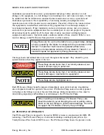
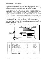
In an SWRO system equipped with PX technology, the main pump is sized to equal the SWRO
permeate flow plus a small amount of bearing lubrication flow, not the full SWRO feed flow.
Therefore, PX technology significantly reduces flow through the main pump. This point is
significant because a reduction in the size of the main pump results in lower operating costs. In
a typical SWRO system equipped with PX technology, the main pump will provide 41% of the
energy, the booster will provide 2% and the PX unit(s) will provide the remaining 57%. Since
the PX energy recovery device uses no external power, the total power savings is 57%
compared to a system with no energy recovery.
It is important to note that the PX unit(s) and associated boost pump are sized for 100% of the
reject flow. The role and size of the main high-pressure pump is reduced to that of a “make-up
pump” to compensate for the water that is exiting the SWRO system as permeate.
5.0 INSTALLATION
The PX Booster Pump should be installed in a dry, sheltered location. Some type of drainage
should be provided beneath the pump to allow standing water to drain when performing
maintenance or repair. See installation drawings in Section 13.0 for pump dimensions,
interface locations and minimum maintenance envelope requirements.
1. Place the PX Booster Pump in an appropriate location and mount the motor securely;
making sure that the base of the unit is permanently supported.
2. Connect the inlet and outlet of the pump to the appropriate points. Proper piping, piping
support, and motor mounts must be implemented to minimize external stresses on all piping
fittings. Flexible couplings should be used for joining fittings and piping. See Section 13.0
for appropriate connection dimensions and specifications. PX Booster Pumps are shipped
with the inlet oriented vertically upward. The inlet housing can be rotated either left or right
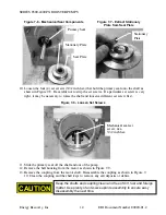
to a horizontal orientation. Remove the four (4) bolts that connect the inlet housing to the
yellow bell housing, rotate the pump head and replace the bolts. Torque bolts to 12 ft-lbs
(16 N-m) as shown in Figure 7-4 below.
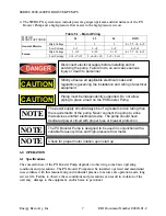
3. Connect the pump motor to a suitable electrical supply. See the motor plate or the inside
cover of the motor electrical junction box for high and low voltage wiring diagrams. If no
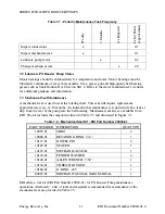
wiring diagram is evident on the motor, refer to Table 5-1. Connect a suitable ground to the
pump motor.
The PX Booster Pump is constructed from AL6XN or
equivalent stainless steel. Inlet and discharge
interconnecting lines should be constructed of suitable
materials to avoid galvanic corrosion.
ERI encourages plant designers and engineers to submit P&IDs to ERI
for engineering review, especially for large or complex SWRO systems.
CAUTION
NOTE


