4S-SERIES PRESSURE EXCHANGER ENERGY RECOVERY DEVICES
Energy Recovery, Inc.
12
ERI Document Number 80022-01-04
•
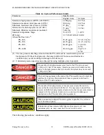
Allowable flow ranges for individual PX units are listed in Table 6-1. PX units are not
designed to operate outside of these ranges.
•
Seawater feed to PX units must be filtered to 5 microns or less and should be subjected to the
same pretreatment as seawater being fed to the SWRO membranes.
•
Entrained or trapped air or other gasses must be purged from the SWRO system before
pressurization. Large bubbles in a pressurized system can result in damage to piping and
equipment including the PX unit.
•
Piping connections to PX units must be designed to minimize stress on the fittings and
vessel.
•
The PX unit vessel-bearing plates (end caps) incorporate interlocking restraining devices.
Deterioration of these devices could lead to catastrophic mechanical failure of the PX unit
enclosure. The PX unit vessel has weep holes drilled through it near the bearing plates to
help keep the vessel heads drained. The vessel heads and weep holes should be regularly
flushed with fresh water or permeate to help prevent salt buildup and corrosion.
•
The PX unit must never be exposed to temperatures less than 33 deg F [1 deg C] or greater
than 120 deg F [49 deg C].
•
Under no circumstances shall the brine inlet pressure (HP IN) exceed 1,200 psig (82.7 bar).
•
The seawater feed inlet pressure shall not exceed 300 psig (20.7 bar). The minimum
discharge pressure from the PX unit shall be 15 psig (1.0 bar).
•
The PX unit(s) must be removed from the SWRO system when performing hydrostatic
testing on piping or other SWRO system components. Never attempt to hydrostatically test a
PX device.
•
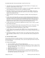
Install piping and fittings so that the PX unit(s) can be isolated from membrane reject flow
during membrane cleaning. Failure to do so may introduce debris that may damage the PX
unit.
6.2 Start and Stop Procedures
The following procedures are general guidelines for the startup and shutdown of PX systems.
Procedure details will vary by plant design. Always ensure the operating limits listed in section
6.1 are not exceeded.
6.2.1 System Start Up Sequence
1.
All valves should be in their normal operating positions.
2.
Start the seawater supply pump. The feed flow through the PX unit may or may not cause
the rotor to begin to rotate. Rotation will produce a humming noise that is audible at close
proximity to the PX unit.
3.
Adjust the seawater flow to the desired flow rate.
4.
Bleed air from the system.
5.
After the PX device has run with seawater for 5 to 10 minutes, start the PX booster
(brine) pump. Rotor speed will increase and remaining air will be released from the PX
unit. Bleed any remaining air from the system.

