background image

4S-SERIES PRESSURE EXCHANGER ENERGY RECOVERY DEVICES 

Energy Recovery, Inc. 

24 

ERI Document Number 80022-01-04


17.


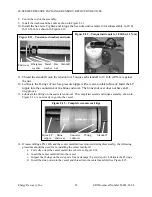
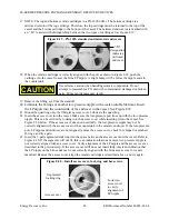
NOTE: The top and bottom ceramic cartridges in a PX-140S differ. The bottom cartridge is a 
mirrored version of the top cartridge. Therefore, the top cartridge must be returned to the top of the 
vessel and the bottom cartridge to the bottom of the vessel. The mirrored endcovers are marked with 
an “-M” to assist with distinguishing between the two types of cartridges. See Figure 8.19. 


18.


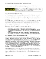
When the ceramic cartridge is correctly aligned with the port as shown in Figure 8.18, push the 
cartridge into the vessel to seat the brine LP nipple. A slight bump will be felt as the nipple seats in 
the countersink.  


19.


Remove the lifting eye from the standoff. 

20.


Lubricate the O-rings of another low-pressure nipple with a water-soluble lubricant. Insert 
the LP nipple into the countersink of the endcover in the vessel. See Figure 8.18. 

21.


Mount the quad ring onto the fiberglass access cover. Lubricate the quad ring. 

22.


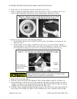
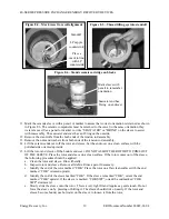
Insert the access cover into the vessel. Make sure the low-pressure port lines up with the low-pressure 
nipple. This can be verified by looking into the access cover while inserting it into the vessel. See 
Figure 8.20 below. If the access cover does not insert fully, the low-pressure nipple may not be 
correctly aligned with the access cover or the countersink in the ceramic endcover. If the low-pressure 
port, LP nipple and endcover are not aligned, remove the access cover, check for chipped or pinched 
O-rings, and try again. 

23.


Insert the 3-part segmented lock ring into the space between the access cover and the vessel. Refer to 
Figure 8.20. If the segments will not fit, this is an indication that one or more low-pressure nipple is 
not correctly aligned with an access cover. Verify alignment of the LP nipple and the access cover as 
described in the previous step. If the access cover still does not insert fully, this is an indication that 
the LP nipple on the brine endcover is not correctly aligned with the brine access cover or center 
manifold. Remove the access cover, align the ceramic cartridge as described above, and try again.  


Figure 8.20 – Install access cover, lock ring and hex screws 

Segmented 

locking ring

Access cover

Look into 
access cover 
to verify 
alignment of 
LP nipple 

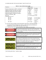
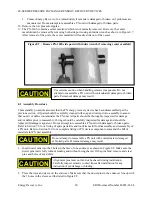
Use extreme caution when handling ceramic components. Do not 
attempt to reassemble a PX unit with contaminated, damaged or broken 
parts. Permanent damage may result. 

Figure 8.19 – PX-140S standard and mirrored endcovers 

“-M” 

designation 

indicates 

mirrored 

endcover 

CAUTION 

Summary of Contents for Pressure Exchanger 4S Series

Page 1: ...N MAINTENANCE MANUAL ERI DOCUMENT NUMBER 80022 01 REVISION 4 ERI 4S Series Pressure Exchanger Energy Recovery Device Energy Recovery Inc 1908 Doolittle Drive San Leandro CA 94577 USA Tel 1 510 483 7370 Fax 1 510 483 7371 www energy recovery com sales energy recovery com Energy Recovery Inc 2004 6 ...

Page 2: ... DESIGN 9 5 0 INSTALLATION 10 6 0 OPERATION 10 6 1 SYSTEM PERFORMANCE SPECIFICATIONS PRECAUTIONS AND CONDITIONS 10 6 2 START AND STOP PROCEDURES 12 6 2 1 SYSTEM START UP SEQUENCE 12 6 2 2 SHORT TERM 1 3 DAYS SYSTEM SHUT DOWN SEQUENCE 13 6 2 3 MEDIUM TERM 4 14 DAYS SYSTEM SHUT DOWN SEQUENCE 13 6 2 4 LONG TERM OVER 2 WEEKS SYSTEM SHUT DOWN SEQUENCE 13 6 2 5 MEMBRANE CLEANING 14 6 3 FLOW CONTROL AND ...

Page 3: ... good judgment in the operation and care of this product and its components The safety officer at the location where this equipment is installed must establish a safety program based on a thorough analysis of local industrial hazards Proper installation and care of shutdown devices and over pressure and over flow protection equipment must be an essential part of any such program In general all per...

Page 4: ...with precise clearances that when filled with high pressure water create an almost frictionless hydrodynamic bearing At any given instant half of the rotor ducts are exposed to the high pressure stream and half the ducts are exposed to the low pressure stream As the rotor turns the ducts pass a sealing area that separates high and low pressure Thus the ducts that contain high pressure are separate...

Page 5: ...rates The issues presented in this and the following sections should be taken into consideration when designing an SWRO system In addition engineers at Energy Recovery Inc are available for design consultation and review of process and instrument diagrams Example flow rates and pressures for an SWRO system with one PX 90S are listed in Table 4 1 below with reference to Figure 4 2 In an SWRO system...

Page 6: ...r Pump Outlet Seawater 78 17 7 1000 69 F SWRO Feed Stream 133 30 2 1000 69 G HP IN to PX Unit Reject 80 18 2 971 67 H LP OUT of PX Unit Reject 80 18 2 15 1 0 I SWRO Product Water 53 12 1 5 0 3 An SWRO system with ERI energy recovery device s can operate efficiently at low recovery rates because PX units replace all of the reject brine flow with a nearly equal volume of feed seawater at up to 97 ef...

Page 7: ...are listed on Energy Recovery Inc s website 4 5 Control of Feed Flow Pressure and Permeate Water Quality The flow rate pressure and quality of the feed streams to the PX unit s must be monitored and controlled Operation and control of a PX unit in an SWRO system can be understood by considering two parallel pipes one of high pressure water and one of low pressure water flowing through the PX unit ...

Page 8: ...pon start up See Section 6 2 for detailed startup and shutdown procedures 4 7 Debris and Initial Flushing Debris and or air in the feed streams to the PX unit can damage the device All piping systems should be flushed prior to initial startup to remove any debris All air must be purged from both the low and high pressure circuits before the system is SWRO pressurized If the SWRO system is to be st...

Page 9: ... large manifold pipe diameters In a sufficiently large manifold the pressure drop along the manifold is much less than the pressure drop through a PX unit such that the manifolds serve as constant pressure reservoirs regardless of flow orientation With a properly designed manifold the PX units in an array naturally distribute flow evenly A sample connection at the low pressure outlet of each PX un...

Page 10: ...and seals Do not use grease Section 13 0 contains an installation diagram piping detail for use for piping manifold and support rack design 6 0 OPERATION 6 1 System Performance Specifications Precautions and Conditions Successful operation of the PX Pressure Exchanger energy recovery device requires observation of some basic operating conditions and precautions The PX unit must be installed operat...

Page 11: ...ge to the device s 2 Unlimited system capacities are achieved by using multiple units in parallel The following precautions conditions apply Introduction of non water soluble films such as grease oil wax petroleum jelly etc may cause the PX unit s rotor to seize The lock ring segments in the ends of the PX assembly must be kept dry and free of corrosion Deterioration of these segments could lead t...

Page 12: ...eg F 49 deg C Under no circumstances shall the brine inlet pressure HP IN exceed 1 200 psig 82 7 bar The seawater feed inlet pressure shall not exceed 300 psig 20 7 bar The minimum discharge pressure from the PX unit shall be 15 psig 1 0 bar The PX unit s must be removed from the SWRO system when performing hydrostatic testing on piping or other SWRO system components Never attempt to hydrostatica...

Page 13: ...ter pump is operating Run the system for 5 to 10 minutes until all the seawater is purged 3 Stop the booster pump 5 Isolate the fresh water supply source 6 2 4 Long Term Over 2 Weeks System Shut Down Sequence If a plant is to be shut down for an extended period of time the SWRO system including the PX units must be thoroughly flushed with fresh water to remove any salt and precautions should be ta...

Page 14: ...w The high pressure flow rate must be verified with a high pressure flow meter 6 3 2 Low Pressure Flow Control The low pressure flow through the PX unit is controlled by the seawater supply pump and a throttle valve in the brine discharge from the PX unit s This valve also adds backpressure on the PX device required to prevent destructive cavitation The low pressure flow rate must be verified with...

Page 15: ... on the booster pump or the high pressure control valve until the desired flow rate is achieved as indicated by the high pressure flow meter 6 3 4 Verification of PX Energy Recovery Device Flow Balance Once the PX energy recovery device has been balanced using flow readings balance can be verified by checking the salinity of the high pressure seawater from the PX unit If the high and low pressure ...

Page 16: ...rated into the SWRO plant design 7 0 SPARE PARTS AND TOOL KITS The PX Pressure Exchanger energy recovery device needs no scheduled periodic maintenance However in the event that the PX unit is disassembled Energy Recovery Inc recommends use of the following ALL 4S Series PXs 4S Tool Kit Energy Recovery Inc Part Number 20023 01 PX 45S 70S 90S 4S Single Rotor Spares Kit Energy Recovery Inc Part Numb...

Page 17: ...edure The procedure provided in this subsection is for complete disassembly of a 4S Series PX energy recovery device Refer to Section 7 0 for a listing of spare parts kits and tool kits useful for disassembly and reassembly of a PX unit For single rotor models PX 45S PX 70S or PX 90S the internal components are reached through the seawater end of the vessel therefore only the seawater access cover...

Page 18: ...ile prying 7 Remove the low pressure nipple 8 Mark the vessel to facilitate correct alignment of the cartridge during reassembly See Figure 8 4 9 Thread the lifting eye bolt 5 16 18 into the standoff on the ceramic cartridge Extract the ceramic cartridge See Figure 8 5 For Single Rotor 4S Series PXs PX 45S PX 70S or PX 90S the ceramic cartridge must be removed from the seawater LP IN HP OUT end 10...

Page 19: ...on a clean surface If the rotor comes out of the sleeve the following procedure should be applied a Clean the rotor and sleeve Rinse liberally b Inspect rotor and sleeve Remove all debris Rinse again if necessary c Identify the end of the rotor marked CHK Place the rotor on a flat clean surface with the end marked CHK oriented upward d Identify the end of the sleeve marked CHK If the sleeve is mar...

Page 20: ...Do not attempt to reassemble a PX unit with damaged or broken parts Refer to Section 7 0 for a listing of spare parts kits and tool kits useful for disassembly and reassembly of a PX unit Refer to Section 13 0 for a complete listing of PX device component names and the bill of materials for PX unit assembly 1 Insert dowel pins into the 3 holes in the face of one endcover as shown in Figure 8 8 Mak...

Page 21: ...ted will prevent the sleeve and the endcover from coming into intimate contact If this occurs remove the rotor and sleeve assembly rinse ceramics and remove all debris Repeat assembly 6 Lubricate the tension rod O rings and the inside of the center hole of both endcovers with a water soluble lubricant such as glycerin or non abrasive liquid soap Do not use grease 7 Insert the tension rod through t...

Page 22: ...e the O ring on the seawater endcover The completed ceramic cartridge assembly shown in Figure 8 13 is now ready to go into the vessel 14 If reassembling a PX 140S and the center manifold was removed during disassembly the following procedure should be used for re installing the center manifold a Correctly orient the center manifold as shown in Figure 8 14 b Insert the center manifold into the ves...

Page 23: ...ter manifold See Figure 8 16 To assist with alignment the seawater endcover has a tick mark that should be centered on the HP OUT port opening See Figure 8 18 Precise alignment of the tick mark with the port will help assure that the brine LP nipple not visible is correctly aligned with the countersink inside the vessel Figure 8 16 Insert ceramic cartridge O ring end goes in last HP OUT port Figur...

Page 24: ...ile inserting it into the vessel See Figure 8 20 below If the access cover does not insert fully the low pressure nipple may not be correctly aligned with the access cover or the countersink in the ceramic endcover If the low pressure port LP nipple and endcover are not aligned remove the access cover check for chipped or pinched O rings and try again 23 Insert the 3 part segmented lock ring into ...

Page 25: ...g with six 6 socket head cap screws 25 Inspect and lubricate the O ring on the LP port Install the LP port into the access cover When handling and installing a PX device care should be taken to avoid dropping the unit or putting undue strain on the port fittings to avoid internal damage Do not lift the PX unit with the ports CAUTION ...

Page 26: ...inistration Department Total number of Pressure Exchangers in parallel _________ Model of Pressure Exchanger s installed ___________________________________ Serial Number s ______________________________________________________________ Units please circle one psi gpm bar m3 hr Date Total Hours HP Inlet Pressure HP Inlet Flow HP Inlet Salinity HP Outlet Pressure HP Outlet Flow HP Outlet Salinity LP...

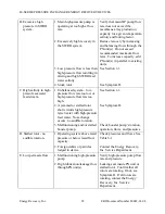
Page 27: ...f malfunctions before performing replacements When using this troubleshooting guide please read all the probable causes before taking any action Use good common sense and the probable cause that most likely fits the given situation Table 9 1 Troubleshooting SYMPTOM PROBABLE CAUSE CORRECTIVE ACTION A Excessive noise levels 1 Operating PX unit s above rated flow rates on low pressure side high press...

Page 28: ...ure seawater feed stream 1 Unbalanced system low pressure flow rate too low or high pressure flow rate too high See Section 6 3 2 A jammed or stalled rotor short circuits high pressure reject water with high pressure feed water No exchange occurs no audible rotation See Symptom D 3 Malfunctioning and or stalled booster pump Check booster pump s rotation operation flows and pressures D Stalled roto...

Page 29: ... DEVICES Energy Recovery Inc 29 ERI Document Number 80022 01 04 F Low reject flow 1 Excessive pressure losses through SWRO system Contact SWRO supplier 2 Malfunctioning and or stalled booster pump Check booster pump operation flows and pressures ...

Page 30: ...d a problem develop with any ERI product the Energy Recovery Inc Technical Services group is prepared to handle customers concerns whether the location is domestic or overseas Service rates are available upon request Energy Recovery Inc 1908 Doolittle Drive San Leandro CA 94577 USA Tel 1 510 483 7370 Fax 1 510 483 7371 Email sales energy recovery com Web www energy recovery com 11 0 REVISION LOG R...

Page 31: ...y shall not exceed an amount equal to the Purchase Price Remedy If a PX unit covered under this Warranty becomes inoperative ERI will at its option either promptly repair or replace the faulty unit Repair or replacement parts will be supplied Ex works San Leandro California without charge to Buyer except that Buyer shall be responsible for applicable taxes duties and installation costs ERI shall e...

Page 32: ...ls that are not acceptable to the SWRO membrane manufacturers for application to the membranes used at the plant are not acceptable to ERI Chemical application levels and frequencies must follow membrane manufacturer s guidelines Buyer will make a list of chemicals and their application criteria doses residence times etc available to ERI In the unlikely event that it does occur Buyer is solely res...

Page 33: ...Energy Recovery Inc 33 ERI Document Number 80022 01 04 13 0 DRAWINGS AND DATA 1 PRESSURE EXCHANGER ASSEMBLY DRAWINGS 2 PROCESS AND INSTRUMENT DIAGRAMS ...

Reviews: