4S-SERIES PRESSURE EXCHANGER ENERGY RECOVERY DEVICES
Energy Recovery, Inc.
6
ERI Document Number 80022-01-04
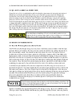
installed, the main high-pressure (HP) pump is sized to equal the SWRO permeate flow plus a
small amount of bearing lubrication flow, not the full SWRO feed flow. Therefore, PX energy
recovery technology significantly reduces flow through the main HP pump. This point is
significant because a reduction in the size of the main HP pump results in lower capital and
operating costs. In a typical SWRO system with a PX unit operating at 40% recovery, the main
HP pump will provide 41% of the energy, the booster will provide 2% and the PX unit will
provide the remaining 57%. Since the PX unit uses no external power, a total power savings of
57% is possible compared to a system with no energy recovery.
Table 4-1. Typical SWRO System Flows and Pressures
STREAM DESCRIPTION
FLOW RATE
GPM / M3/HR
PRESSURE.
PSI / BAR
A
Seawater Supply
133 / 30.2
25 / 1.7
B
LP IN to PX Unit / Seawater
78 / 17.7
25 / 1.7
C
Main HP Pump outlet
55 / 12.6
1000 / 69
D
HP OUT of PX Unit / Seawater
78 / 17.7
957 / 66
E
Booster Pump Outlet / Seawater
78 / 17.7
1000 / 69
F
SWRO Feed Stream
133 / 30.2
1000 / 69
G
HP IN to PX Unit / Reject
80 / 18.2
971 / 67
H
LP OUT of PX Unit / Reject
80 / 18.2
15 / 1.0
I
SWRO Product Water
53 / 12.1
5 / 0.3
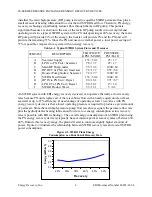
An SWRO system with ERI energy recovery device(s) can operate efficiently at low recovery
rates because PX units replace all of the reject-brine flow with a nearly equal volume of feed-
seawater at up to 97% efficiency. One advantage of operating at lower recoveries with PX
energy recovery devices is that a lower operating pressure is required to produce a given amount
of permeate. Since the main high-pressure-pump flow rate always equals the permeate flow rate
plus the hydrodynamic bearing lubrication flow rate, low energy consumption at low recovery
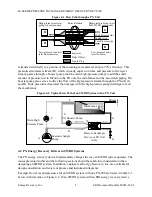
rates is possible with ERI technology. The overall energy consumption of an SWRO plant using
the PX energy recovery device(s) typically has a minimum point at recovery rates of between 30-
40%. Outside this recovery range, the plant will start to consume slightly higher amounts of
power. Figure 4-3 illustrates the relationship between SWRO recovery rate and overall SWRO
power consumption.
2.0
2.2
2.4
2.6
2.8
3.0
25%
30%
35%
40%
45%
50%
Recovery
E
n
er
g
y
(
k
Wh
/m
3)
Figure 4-3. SWRO Plant Energy
Consumption as a Function of Recovery Rate

