26
b.
Place Mode display in the Instantaneous (id) mode.
c.
Turn on a large (greater that 5 KW) uncontrolled load
such as the kitchen range. Leave all controlled loads off.
Caution:
Please take all necessary precautions to
prevent damage or injury from the hot surfaces on
the stove top. Do not leave elements on more than the
brief amount of time it takes to run this test.
d.
Within 3 minutes, all Circuit On LED indicators
on the Control/Display Unit should turn off (unless
Minimum On-Times are programmed) and the alarm
should sound.
e.
Increase the demand limit setting 1 KW at a time until
the alarm stops. The demand limit should be slightly
larger than the amount of KW of the uncontrolled load.
This verifi es that the unit is measuring power properly.
f.
Turn off the uncontrolled load.
17.4 Power On-Test
a.
Ensure all circuit breakers in the circuit breaker panel
are off except for the 15 AMP circuit breaker labeled
“Energy Sentry” or “9312”.
b. Set the demand limit to a number 2-3 times h i g h e r
than the estimated demand limit of the installation
(i.e. if you intend to control at 6 KW, set the 9312 to
12-18 KW).
c.
This demand limit will allow all of the circuits
to be restored in about 1 minute per circuit, once the
restoring process begins.
d. Turn on each controlled load circuit, one at a time.
Immediately proceed to 17.5 Shed Test without
delay.
Caution:
Do not leave controlled loads on for more
than a few minutes as this may cause the electric meter to
register a high demand peak.
Note:
If Minimum On and Off-Times have been pro-
grammed into the unit, then loads controlled under these
times will switch only when the appropriate time intervals
have elapsed.
17.5 Shed Test
a.
Set demand limit to 2 KW
b.
The unit will begin to shed loads (because all the
controlled loads are causing a high instantaneous
demand) starting with the lowest priority load
and ending with the highest priority load. Once
all loads are shed, the alarm will sound because
the demand level is most likely still above the
demand limit of 2 KW. When this happens, set
the demand limit to its normal level (apx 6-8 KW
or whatever it may be for your specifi c home at
that time of the year) and the alarm should stop.
17.6
Restore household loads to the desired condition.
The circuit breaker marked “Energy Sentry” or “9312”
should be left on with the desired demand limit set into the
Control/Display Unit.
18.0 System Program-
ming
The system programming mode of the 9312 is designed
to give the user ultimate fl exibility in “tailoring” the 9312’s
operation to the user’s exact requirements. In this mode,
the user programs the 9312 through the Control/Display
front panel and answers a series of questions which tell the
system: 1.) Day, Month, and Year; 2.) On-Peak and Off-
Peak controlling times; 3.) How many relays are connected
to the system; 4.) What load control strategy (priorities) it
will operate under; and 5.) The Minimum On/Off-Times
for all 16 control points, if times are required.
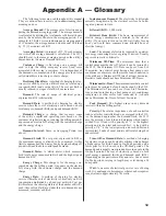
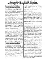
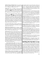
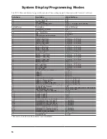
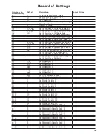
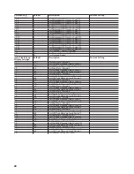
Appendix B explains the different settings and includes
a list of the settings as they occur.
It is the user’s responsi-
bility to maintain the correct time-of-day, day-of-week,
date, holiday, and all other system settings which affect
the system’s proper operation.
It is recommended to
check the time at least once a month and adjust as neces-
sary.
19.0 Wrap-Up
19.1
The Energy Sentry 9312 should now be ON and all
circuit breakers for loads controlled by the Energy Sentry
should also be on.
19.2
The 9312 should now be set with the proper system
settings. Air conditioners and heat pump compressors must
have Minimum Off-Times of at least 4 minutes.
19.3
Control/Display Unit should display Instantaneous
(id), Average (Ad), and Peak demand (pd) power readings.
Circuit On LED indicators should show which loads are
enabled.
19.4
Relays in Relay Unit(s) should be turning loads on and
off as necessary.
19.5
Replace cover on the 9312’s Relay Unit and on the
circuit breaker panel.
19.6
Record the following information in the spaces pro-
vided in Section 20:

