background image

17 

4. Installation of Boiler Components

With the vessel in place, you are ready to attach the vessel panels and insulation, the wire 
harness and controls, the optional domestic coil, and the burner/preheater assembly. Then, 
you will install the fuel tubing from the pump discharge to the preheater. Finally, your hydronics 
professional will connect the hydronic piping system to the boiler 

– and fill the system. 

4.1  Vessel Panel and Insulation Assembly 

Install the vessel panels and insulation as follows: 

1. Open the box containing the insulation, panels, and hardware.
2. Wrap the insulation around the boiler vessel. Use the ribbon provided to secure the

insulation around the vessel. Install the insulation for the front panel. Note: Make sure to
cut out the insulation for ports and drains as needed. On front panel, make sure that the
insulation is cut out to provide a view of the ASME boiler plate.

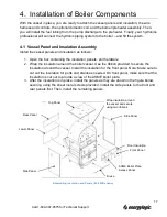
3. After the insulation is in place, install the panels as they are shown in the figure below,

securing using the sheet metal screws provided. Install the side panels to the front and
rear panels first. Then, install the remaining panels.

Side Panel 

Wrap insulation around 
the vessel and secure 
using two ribbons. 

Front Panel 

Front Insulation 

ASME Boiler Plate 
Access Panel. 

Brace 

Side Panel 

Rear Panel 

Lower Panel 

Top Panel 

Assembling Insulation and Panels (EL-200B shown)

Call 1-

800-347-9575

 for Technical Support

Summary of Contents for EL-200B

Page 1: ...Item 98030034 Issue date 26 March 2014 Installation Operation Manual EL 200B EL 375B and EL 500B 115V 60Hz ASME Certified Designed to save Built to last...

Page 2: ...ide installation service parts and support for your EnergyLogic systems If you have any questions issues or problems please feel free to call us for technical support or parts We also offer various ma...

Page 3: ...installation practice shall be made according to CSA standard B139 Installation Code for Oil Burning Equipment Product improvements are occurring regularly so the products may vary slightly from what...

Page 4: ...3 Boiler Vessel Installation 12 3 3 1 Vessel Installation 12 3 4 Preparing the EnergyLogic Used Oil Tank 13 3 4 1 Tank Vent Installation EnergyLogic Tanks 13 3 4 2 Drain Valve Installation EnergyLogi...

Page 5: ...1 Hydronics Installation Key Points 28 4 8 2 Hydronics Set Up 29 4 8 3 Boiler Mixing Valve Set Up 30 4 9 Filling the System 30 5 Exhaust Flue System Installation 31 5 1 Barometric Damper Tee Installat...

Page 6: ...8 5 8 Air Compressor Maintenance 64 8 6 Seasonal Shut Down Start Up 66 9 Troubleshooting 67 9 1 Troubleshooting Condition Table 68 9 2 Troubleshooting Trees 69 9 3 Testing Procedures 72 9 3 1 Wall Th...

Page 7: ...For your safety this manual uses the following definitions and signal words to identify hazards Danger Indicates an imminently hazardous situation which if not avoided will result in death or serious...

Page 8: ...D FROM OR DEPOSITED WITHIN THIS HEATING APPLIANCE AND THEREFORE CARE SHOULD BE TAKEN WHEN USING CLEANING AND MAINTAINING THIS EQUIPMENT EnergyLogic recommends that the building domestic hot water syst...

Page 9: ...safety glasses and a dust mask or respirator whenever any cleaning is performed including the cleaning of the heat exchanger flue piping and exhaust stack Vapor Dust Ignition Do not store or use gasol...

Page 10: ...ith all the regulation authorities having jurisdiction as well as CSA Standard B 139 Installation Code for Oil Burning Equipment B140 0 General Requirements for Oil Burning Equipment B140 7 2 Oil Fire...

Page 11: ...are not limited to Gasoline Kerosene Hazardous Waste Anti freeze Carburetor Cleaner Paint Thinner Any Chlorinated Material Parts Washer Solvents Oil Additives Animal Fats Brake Fluid The addition of i...

Page 12: ...es may result in fire explosion personal injury or death The U L Listing specifies For all boilers rated for 50 psi or less and for all water boilers installation clearances are Form III The boilers a...

Page 13: ...o cold weather If this is not practical call EnergyLogic for application support 7 Locate boiler and tank in a dry area above 50 F 10 C at all times 8 If not installing the pump to an EnergyLogic Tank...

Page 14: ...electrician In the U S consult the National Electric Code NEC and local building codes for additional requirements In Canada consult the Canadian Electrical Code Part I Flue Pipe Is ceiling roof or wa...

Page 15: ...m property line shall be in accordance with the authorities having jurisdiction concerning environmental quality as well as fuel fire and electrical safety and Table 7 in CSA B140 0 03 clause 22 3 2 O...

Page 16: ...t EnergyLogic If any parts were damaged during shipment please contact your shipping carrier 3 2 Warranty Registration IMPORTANT You must register your boiler with EnergyLogic for the warranty to beco...

Page 17: ...and Tee Assembly 1 12 Draft Gauge provided with bundles only 1 13 Draft Gauge Probe provided with bundles only 1 14 Thread Sealant Tube not shown 1 15 EnergyLogic Workbench Tank 1 16 Drain Valve Assem...

Page 18: ...This is to be found in the rear breech chimney connector 4 Consider the following Prior to placement a licensed electrician shall install a dedicated 115vac 60Hz service junction box switchable and l...

Page 19: ...along the bottom of the tank as shown in figure Use the provided thread sealer on the threads during installation Note Some tanks come with the drain valve already installed The drain valve is necess...

Page 20: ...NPT fitting and screw the fire stop valve to the fuel filter head fully tighten the NPT threads using a back up wrench Then apply sealer to the NPT fitting and screw the entire filter head assembly wi...

Page 21: ...sure gauge on the outlet tee and the combination vacuum pressure gauge on the inlet tee 3 Locate the short 3 8 copper tube assembly Carefully bend the tube without kinking into position as shown 4 Thr...

Page 22: ...in 6 of the tank The ideal placement of pump is with the inlet above the filter head assembly which should be mounted above the tank fitting Maximum vertical lift for the suction line should not excee...

Page 23: ...vessel Use the ribbon provided to secure the insulation around the vessel Install the insulation for the front panel Note Make sure to cut out the insulation for ports and drains as needed On front p...

Page 24: ...ontact is necessary for proper electrical conduction and function of the probe 3 Thread the probe into the port Do not use grease on this probe Tighten Align the probe so that the mounting screws are...

Page 25: ...er Installation 1 Remove the cover from the triple aquastat control 2 Fill the triple aquastat thermal well refer to figures with thermal conductive grease provided as follows Fold the plastic bag of...

Page 26: ...mit and its fixed differential of 10 F and the water circulation pump will be powered if this control is used for the circulation pump 7 If using the circulation pump control on the aquastat wire the...

Page 27: ...probe opening 5 Make sure that the control is set to 230 F Do not increase the setting 6 Install the cover to the control 4 2 4 Vessel Wire Box installation 1 Mount the wire box to the upper right fr...

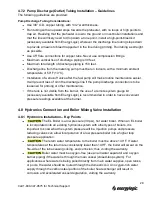
Page 28: ...from the relief valve routed according to code to a safe place for discharge 2 Install the combination temperature pressure gauge in the port shown in the beginning of this section Use pipe dope on th...

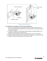
Page 29: ...valve and preheater as shown in the figure 4 Tighten the fuel tubing fittings and the long preheater bolt 5 Screw the plug end of the conduit into the receptacle on the burner wire box 6 Install the...

Page 30: ...es for proper settings refer to Section 8 5 6 4 Mount the burner assembly onto the vessel by inserting the burner over the studs 5 Reinstall and tighten the four 4 nuts 6 Plug the burner harness into...

Page 31: ...d 8 Thread do not tighten the small copper tube assembly onto the flare fittings on the preheater solenoid valve and burner air tube 9 Tighten the fuel tubing fittings and the long preheater bolt Do n...

Page 32: ...Fitting on Side of Burner Air Tube Plug in burner plug Install nuts and tighten Install Burner Install Burner Gasket Plug in preheater Install Air Filter Install Copper Fuel Tube on Preheater End and...

Page 33: ...flare fitting over one end of the copper tubing and use a flaring tool to flare the end of the tube Make sure the flare is smooth with no cracks 4 Thread do not tighten the flare fitting to the fuel...

Page 34: ...other maintenance If the tank is not visible from the burner the use of a remote system gauge kit accessory available from EnergyLogic is recommended in order to have convenient pressure readings avai...

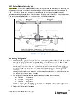
Page 35: ...m expansion tank used to prevent system pressure spikes as the loop water temperature increases Size this accordingly based on the BTU net output Air water separator used to remove air from the initia...

Page 36: ...m piping is complete add heating grade antifreeze into the vessel through the gauge port on the top prior to filling the system with water A 25 to 50 solution is typical however the climate of use wil...

Page 37: ...about your ability to complete the installation in a safe and workmanlike manner you should arrange for a professional installation For more regulatory information regarding flue pipe installation con...

Page 38: ...herence to the instructions will fully comply with national safety standards such as NFPA 31 54 and 211 Refer to fire and building codes for further requirements Improper installation of the flue syst...

Page 39: ...ustion air to the burner which may result in a hazard from smoke inhalation and or fire Use of exhaust fans in your shop without adequate make up air may create a negative pressure There are other pos...

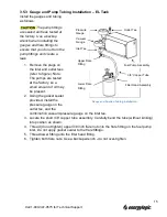
Page 40: ...plastic tube packaged with the gauge to the draft gauge port labeled Low at top of the gauge Note By doing this the negative readings will now read positive on the gauge scale This is to take advantag...

Page 41: ...ional Accessories 6 1 1 Wall Thermostat Installation The wall thermostat signals to the triple aquastat temperature controller when a call for heat is required Refer to section 4 2 on the installation...

Page 42: ...s remote from the boiler you will need to extend the pump wiring If so use the same gauge 14 AWG of wire that is in the factory pump conduit at a minimum Use copper conductors only and wire to code 3...

Page 43: ...he box be switchable with a lock out feature Verify the use of a dedicated circuit 115VAC single phase circuit breaker 25Amp maximum per UL wired to code for the size and type of service used Make sur...

Page 44: ...Only use EnergyLogic fuel filters with 140 micron metal mesh specifications Do not use paper element filters 11 PERFORM THE RECOMMENDED PERIODIC MAINTENANCE 12 Unplug the burner during the off season...

Page 45: ...arts the combustion air blower and compressor 4 The ignition transformer is powered to spark the igniter 5 The fuel pump turns on and the solenoid valve opens to start delivering fuel 6 Within 15 seco...

Page 46: ...hold the button down for one minute to get the control to reset Multiple resets may allow oil to accumulate in the heat exchanger therefore do not reset more than one or two times Call for service fr...

Page 47: ...tered used oil or non synthetic new ATF to speed the priming process and to reduce amount of air in system Hand tighten the filter apply thin film of oil to gasket 4 Switch on the main power to the bo...

Page 48: ...uel is flowing steadily from the bleed line with to air bubbles reopen the preheater valve and close the bleed valve 15 Once fuel is flowing steadily from the tube at the top of the preheater into the...

Page 49: ...y and there are no exhaust leaks inside the building Check the outside flue pipe to ensure that no black smoke is present If smoke is present and the draft below is correct call EnergyLogic Technical...

Page 50: ...ner Look for crimped tubing or obstructions in the preheater or nozzle block assembly Repair as necessary Vacuum Gauge The vacuum gauge on the inlet of the pump should read between 0 and 5 inches of m...

Page 51: ...n the locking screws A higher number allows more air into the burner A lower number setting allows less air The factory recommended settings normally work well but higher altitude locations may requir...

Page 52: ...pproved substances into your used oil storage tank See section 1 5 1 for a list of approved fuels Monitor the bottom of your tank for water and drain it off on a regular basis Don t let your oil tank...

Page 53: ...rush kit PN 05000071 an EnergyLogic furnace cleaning tool PN 14033227 and boiler tube and flue brushes call for info are the best tools to use for maintenance Compressor maintenance annually Clean pre...

Page 54: ...tem Performance over Time EnergyLogic recommends that you monitor and record your system gauge readings regularly over time in order to diagnose issues that may arise For example if the pump vacuum ga...

Page 55: ...49 Call 1 800 347 9575 for Technical Support...

Page 56: ...at least once every 5 years Tools Required 5 16 in 1 2 in sockets 3 4 in open ended wrench EnergyLogic Furnace Cleaning Tool PN 14033227 chimney brush pipe brushes work gloves dust mask and safety gla...

Page 57: ...l before servicing The panel will have ash build up on it so position a box underneath it to catch the ash 8 Gently clean the damper and draft gage tube Gently tap the flue pipe and allow ash to fall...

Page 58: ...t power at breaker Allow the vessel control and surrounding area to cool below 80 F 4 Remove the low water cut off control cover screws Remove the cover 5 Remove the wing nut and the lead wire from th...

Page 59: ...reen and red lights will flash simultaneously four 4 times The green light will remain on and the red light will turn off The boiler will be ready for operation provided there is water on the probe EL...

Page 60: ...at the filter head 3 Spin the Fuel Filter off the Filter Head Assembly counter clockwise Dispose of the fuel filter properly 4 Clean any debris from the filter head assembly 5 Fill new Fuel Filter wi...

Page 61: ...dels refer to figures 1 Wear all safety equipment 2 Unplug the burner at the vessel wiring box 3 Disconnect the Preheater Connector at the Burner allow it to cool Until the preheater has cooled the pa...

Page 62: ...the process 10 Clean the housing and Top Cap with parts washer fluid 11 Unscrew the Bottom Cap inlet from the housing 12 Remove the old gasket from the cap 13 Clean the cap and valve then replace the...

Page 63: ...zle PN 20210123 for EL 200B PN 20210124 for EL375B EL500B Personally verify that the main power is turned off and locked out at the circuit breaker Procedure All Models Refer to figures 1 Wear all saf...

Page 64: ...10 Remove the Retention Head by loosening the collar set screw 11 Slide the Air Vane off the Nozzle Line Assembly 12 Using a 5 8 in socket ratchet remove the Nozzle from the Nozzle Block Assembly Set...

Page 65: ...ler during reinstallation refer to figure 19 IMPORTANT Being careful not to apply parts washer fluid to the heater wiring harness clean the nozzle passage of the Nozzle Block Make sure parts are clean...

Page 66: ...ons The Electrode Gap 3 32 2 4 mm Electrode Tips must be 1 16 1 6 mm behind the tip of the Nozzle Nozzle protrudes approximately 1 8 3 mm beyond Retention Head vanes Vertical location of electrode wir...

Page 67: ...the nozzle end It should be locked in place by the retention head base For the Double Bend electrodes the retention head should be installed with one leg vertical and the electrodes straddle that leg...

Page 68: ...nd of the fuel tubing at the preheater and burner nozzle block Rotate any tubing out of the way 4 Remove the E Clip from the top of the solenoid Slide the solenoid body and stem from the bottom of the...

Page 69: ...n additional solenoid valve on the fuel metering pump Service this valve whenever the burner solenoid valve is serviced 13 Make sure to perform start up 7 4 2 and system checks 7 4 3 after every maint...

Page 70: ...s in the tubing 4 Start the burner by moving the wall thermostat above room temperature and note the air compressor output on the gauge If the gauge reading is in the 9 11 PSI range for the EL 200B or...

Page 71: ...ble the air compressor Be careful not to over tighten the cover plate C Cleaning Wear Safety Glasses 1 Disconnect the fitting at the air compressor outlet 2 Disconnect the preheater outlet tubing from...

Page 72: ...eheater inlet 4 Open the preheater valve and drain the oil from the preheater 5 Perform annual maintenance Refer to maintenance log 6 Leave the boiler door open slightly Start Up Procedure 1 Inspect t...

Page 73: ...d results from changes made to the building or structure Common things to verify are a Is the fuel in the tank low Has it run dry and the pump lost prime b Has the water in the boiler run low c Fuel P...

Page 74: ...ction 9 2 04 Smoke is seen from the external flue cap or internal damper or the boiler is running rough 1 Go to Section 9 1 Item 3 1 Pump Filter See Section 9 2 2 Go to Section 9 1 item 2 1 Wall T Sta...

Page 75: ...wheel Yes Go to Next Component No Verify operational status by following the steps in the Air Compressor Maintenance in Section 8 5 8 starting with section B of the Procedure If okay replace burner m...

Page 76: ...s running Yes Go to Next Action Question Component No See Metering Pump Assembly Testing in Section 9 3 2 Check Fuel Pressure Turn boiler on or reset the red button of the primary control What is the...

Page 77: ...e no evidence of leaks try soap and air pressure test on the suction side lines by pressurizing at the inlet through the 3 8 inch copper line that leaves the fire stop valve at the tank Yes Repair Rep...

Page 78: ...stat Procedure 1 Disconnect the jumper wire or low fuel cut off wires from the burner by removing the T Stat plug see image below and verify the pins on the plug and receptacle are straight and secure...

Page 79: ...aquastat 2 Allow the burner to heat the boiler vessel until the temperature in the vessel is above the low limit setting plus differential setting minus 10 F Above this temperature the pump will be ca...

Page 80: ...ell Procedure 1 Unplug the burner plug from its receptacle 2 Loosen or remove two ignition transformer screws The cad cell is located on the underside of the ignition transformer Lift the ignition tra...

Page 81: ...the shafts pump and gear box If worn or damaged replace 4 Verify the gear box model number to the EnergyLogic model number Refer to the following table 5 Jumper the T T terminals as soon as you hear t...

Page 82: ...fire stop valve and push down on the stem Or close ball valve 13 Run pump until the vacuum gauge reads 15 in Hg should quickly reach and stop pump 14 Cap the discharge side of the pump and note the va...

Page 83: ...onents will be energized Only a certified electrician is to perform the following procedures and with extreme caution Procedure 1 With the burner unplugged verify the pins at the preheater plug and re...

Page 84: ...s of the preheater plug refer to figure If the preheater is hot but there is no continuity across the thermostat pins the preheater will need to be replaced 7 If the burner does not light off well the...

Page 85: ...rol 4 Use the alligator clip or jumper wire to connect the T T terminals a Burner should run for several seconds and then trip requiring reset If this happens the primary control is working properly b...

Page 86: ...e and white of the same gauge and remove from terminal strip 4 Using a multi meter test for continuity across the solenoid wires There should be continuity across wires 5 Leaving the purple and white...

Page 87: ...ll Technical Services for assistance Note To check low fuel cut off function see Thermostat Testing Section 9 3 1 Procedure 1 Run the pump vacuum check Section 9 3 4 steps 12 16 and make sure that you...

Page 88: ...for heat When the burner starts jumper the F F terminals on the primary control 4 Find the Black wires coming from the transformer and cautiously check the voltage across the terminals Should read be...

Page 89: ...as in step 11 iii Using the amp clamp around the wire read the amperes 1 Reading should be between 20mA and 26mA with a nominal of 23mA transformer should be labeled 13 Remove jumpers from T T and F...

Page 90: ...orm the following procedures and with extreme caution Procedure 1 Make sure that the Low Water Cut Off Control and High Temperature Limit Aquastat reset buttons are reset pushed in 2 Make sure that th...

Page 91: ...limit control 2 No voltage Go to next step iv Check for voltage at Low Water Cut Off Control press reset button first 1 115 volts across terminals 2 and 5 Shut off power to unit and fix wiring connect...

Page 92: ...86 Call 1 800 347 9575 for Technical Support 10 Appendices 10 1 Boiler Wiring and Oil Schematic...
Page 93: ...87 Call 1 800 347 9575 for Technical Support...

Page 94: ...Support Preheater Plug Pin Diagram Oil Schematic Wide Key at Top Standby Heater Neutral Standby Heater 115V Preheater Thermostat Run Heaters 115V Run Heaters Neutral Center Pin Not Used on 200B Used...

Page 95: ...re 9 11 PSI 13 15 PSI 13 15 PSI Circulator Pump To fit application To fit application To fit application Maximum Fuse Size 25A 25A 25A Burner Motor 1 5 HP 115V 60Hz 3 3A 1 4 HP 115V 60Hz 3 5A 1 4 HP 1...

Page 96: ...90 Call 1 800 347 9575 for Technical Support...

Page 97: ...91 Call 1 800 347 9575 for Technical Support...

Page 98: ...92 Call 1 800 347 9575 for Technical Support...

Page 99: ...torage or use in conjunction with other parts not authorized by MANUFACTURER 9 Products that have been moved from the original installation site or that have been sold or exchanged to a person other t...

Reviews: