35
Call 1-
800-347-9575
for Technical Support
6. Electrical System Installation
Power requirements: a dedicated, hard wired 115VAC/60Hz circuit with a 25amp maximum
circuit breaker. Verify voltage is 115VAC at dedicated breaker prior to connecting to boiler. Use
copper conductors only. A wiring diagram is provided in the Appendices.
Electricity is very dangerous. Wiring should be completed by a qualified electrician. Consult the
National Electric Code (NEC) and local codes for additional requirements. In Canada, consult
the Canadian Electrical Code, Part I.
6.1 Wall Thermostat and Low Fuel Cut-Off Switch Installation (Optional
Accessories)
6.1.1 Wall Thermostat Installation
The wall thermostat signals to the triple aquastat temperature controller when a call for heat is
required. Refer to section 4.2 on the installation of the triple aquastat controller. If using a
thermostat, the factory-installed jumper wire will need to be removed from the triple aquastat
controller, and the thermostat wiring will be installed across the thermostat terminals on the
aquastat temperature controller.
6.1.2 Low Fuel Cut-Off Installation
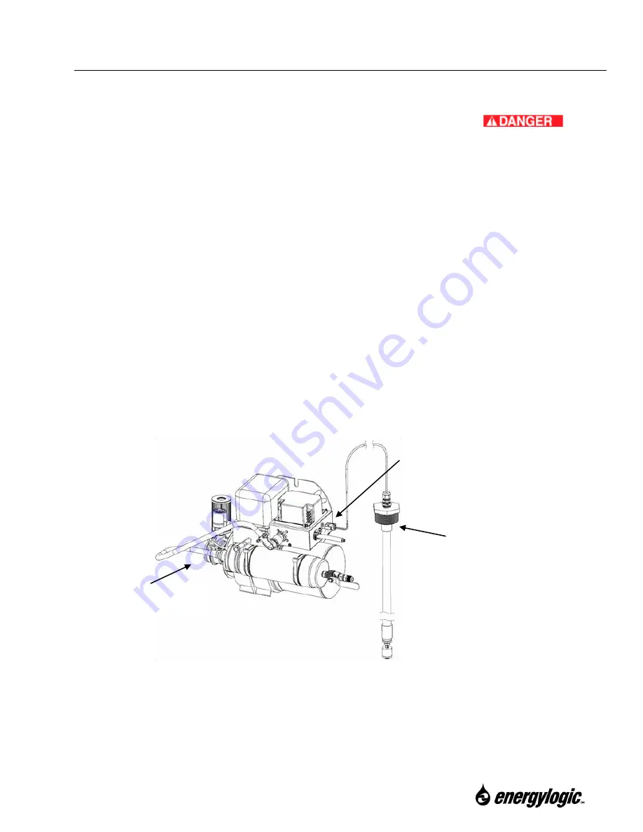
The burner wiring box has a thermostat plug (jumpered). If a low fuel cut-off switch is installed
in the fuel tank, the switch wiring will need to be connected at the burner thermostat plug as
follows.
Low Fuel Cut Off Switch
(Inside of Fuel Tank)
Burner (On Boiler)
Burner Thermostat Plug
Low Fuel Cut Off Installation.

