60
Call 1-
800-347-9575
for Technical Support
8.5.6 Retention Head and Electrode Settings
How often?
Once per year (refer to 8.5.5, Nozzle Line Cleaning)
Procedure
- All Models.
NOTE:
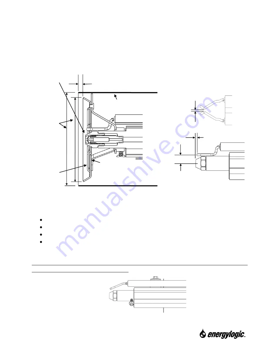
There are two Electrode/Retention Head designs: one where the
electrodes wires make two 90 degree bend
s (called “Double Bend”), and one with a single angled
bend. The “Single Bend” design only goes with Retention Heads with the added center cutout.
Refer to Section 8.5.5 for removal of nozzle block and electrode assembly.
Inspect the
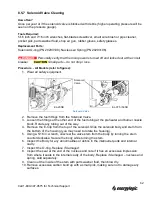
locations of the electrode components. If adjustments are necessary, use needle-nose pliers to
carefully adjust electrode wires. Use the following specifications:
The Electrode Gap:
3/32” (2.4 mm).
Electrode Tips must be 1/1
6” (1.6 mm) behind the tip of the Nozzle.
Nozzle protrudes approximately 1/8
” (3 mm) beyond Retention Head vanes.
Vertical location of electrode wires: 7/16” (1.6 mm) from center nozzle to wires. Make
sure that there is a gap between the electrode wires and the nozzle. Make sure there is
a gap between the retention head inner diameter and the electrode wires.
NOTE:
For the
“Single Bend” electrode, the same settings are used, but the electrode wires
come down at an angle, as shown below.
3/32” (2.4
mm) Gap
1/16” (1.6 mm)
(Electrode behind tip)
1/16” – 1/8” (Flame Retention Head recessed inside Air Tube)
(1.5
– 3 mm)
Retention Head
Air Tube
Center
Retention
Head
within Air
Tube.
Nozzle must
extend
approx. 1/16
to 1/8” (1.5 to
3 mm) beyond
air vanes.
Air Vanes
Settings for Retention Head & Electrodes
– “Double Bend” Electrodes
7/16” (11 mm)

