72
Call 1-
800-347-9575
for Technical Support
9.3 Testing Procedures
Only qualified servicemen are to perform the testing procedures. Many of the
tests involve high voltage electricity, which if mishandled may cause serious injury or death.
9.3.1 Wall Thermostat (if equipped) and Burner Thermostat Circuit Testing
Tools Needed:
Digital Multi-Meter
Wall Thermostat Function:
Monitors the temperature of the room and compares it to the set desired temperature. When
the room temperature falls below the desired, it sends a signal (by closing a switch providing
continuity) to the Triple Aquastat controller - initiating the call for heat.
Note:
During this test, if the thermostat does not function as stated, call Technical Services for
assistance, or Customer Service to order a new thermostat.
Procedure:
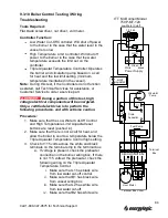
1. Disconnect the jumper wire (or low fuel cut-off wires) from the burner by removing the T-
Stat plug (see image below) and verify the pins on the plug and receptacle are straight
and secure.
2. If the system has a Fuel Low Cutoff Switch
a. Verify the fuel level in the tank is above the switch float. If not, then fill.
b. Check for continuity across the wires of the float switch.
If no continuity, remove the fuel switch and verify when the float is in the up
position, the continuity status. No continuity = replace switch, Continuity =
check fuel status
3. Disconnect the Thermostat wire from the triple aquastat. Set the thermostat to a
temperature high enough to call for heat.
4. Using the ohm meter, connect the leads to each end of the T-Stat wires.
5. You should see continuity across the leads, check the wire connections at the
thermostat and recheck.
T-Stat
Jumper
Model
200B
375B
500B
Pump Shaft Speed
Gear Box Model
115V
241 - 300
483 - 600
161 - 200
115V
3GN6KA
3GN3KA
3GN9KA


