75
Call 1-
800-347-9575
for Technical Support
9.3.4 Metering Pump Assembly Testing
Tools Required:
1/8” Allen wrench, 3/4” wrench, Flat-blade screwdriver, 120VAC capable Digital Multi-Meter,
alligator clips or a jumper wire, Tachometer, stop watch and a graduated cylinder (ounce or
milliliter).
Metering Pump Assembly Function:
Pumps fuel from the tank to the preheater and burner during the call for heat (given the
preheater is up to temperature)
Note:
During this test, if the Pump Assembly does not function as stated, call Technical
Services for assistance, or Customer Service to order service parts.
During a portion of this test, high voltage electrical components will be
energized. Only a certified electrician is to perform the following procedures, and with
extreme caution.
Procedure:
1.
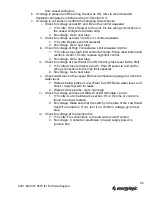
Remove the pump assembly cover.
2.
Inspect the coupler for damage or wear and make sure the set screws are tight and
positioned on the flats of the two shafts. If worn or damaged, replace.
3.
Inspect the condition of, and rotate by hand, the shafts (pump and gear box). If worn or
damaged, replace.
4.
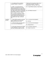
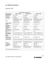
Verify the gear box model number to the EnergyLogic model number. Refer to the
following table.
5.
Jumper the T-T terminals, as soon as you hear the burner start, jumper the F-F
terminals.
6.
Use Caution when approaching the pump assembly, rotating parts will be
in operation.
7.
Chattering from the gear box usually means damaged gearing. If chattering is heard or
felt, replace the gear box.
8.
Close the ball valve at the bottom of the preheater.
9.
Using a multi-meter, verify the voltage across the wires going to the pump motor, should
be around 115V AC.
a.
If voltage is not present, check the wires from the pump conduit to the wiring box and
in the primary control to ensure a secure fit and connections are proper (refer to
wiring diagram for wire location and colors).
b.
If voltage is present, but the motor does not function
i. Remove jumper terminals from the T-T and F-F terminals.
ii. Unhook the pink wire from the pump motor capacitor and hook it into the conduit
wire feeding the black wire going to the capacitor.
iii. Jumper the primary as in Step 5.
Model
200B
375B
500B
Pump Shaft Speed
Gear Box Model
115V
241 - 300
483 - 600
161 - 200
115V
3GN6KA
3GN3KA
3GN9KA


