


14
• Cutter surfaces can become very hot. To prevent
burns, avoid contact with cutter components and
wear appropriate personal protective equipment.
• Refer to additional safety precautions in Section 1.0
of this manual before using the cutter or performing
any maintenance or repair activities.
9.3 Trapped Air Removal
Before placing a new cutter into operation, cycle the
piston several times without load to remove any trapped
air in the hydraulic circuit.
Air is completely purged when the piston advances and
retracts smoothly in both directions, from fully advanced
to fully retracted.
This procedure should be performed after the oil in the
cutter is changed, and after any maintenance or repair
activity in which the oil is drained and replaced.
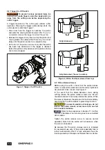
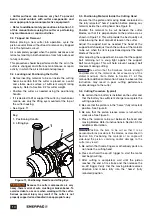
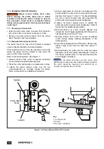
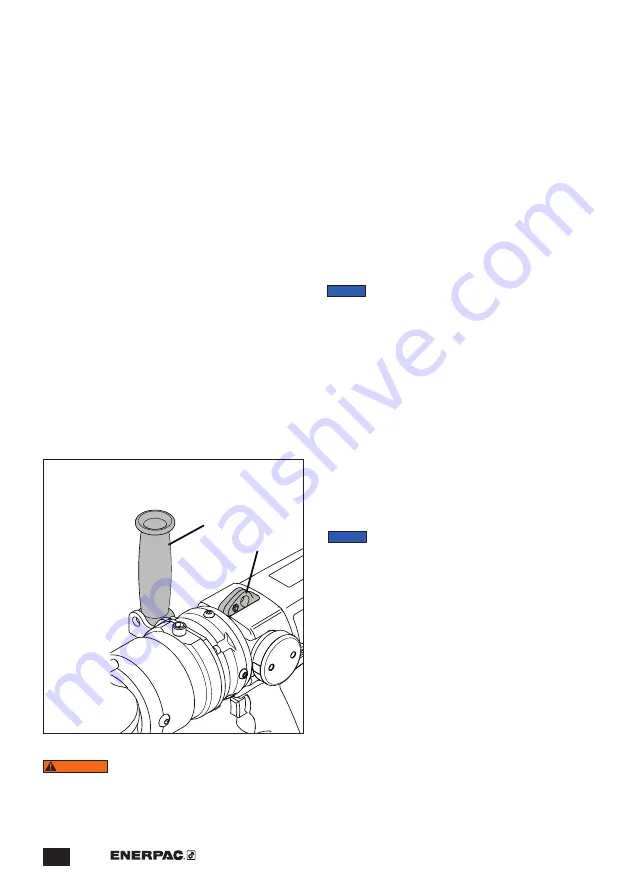
9.4 Locating and Positioning the Cutter
• Before inserting material to be cut inside the cutting
head, be certain that the cutter is placed on a solid
and stable work surface of sufficient weight rating
capacity. Refer to Section 2.2 for cutter weight.
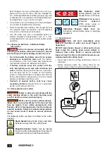
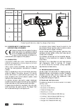
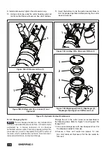
• Position the cutter as needed using the positioning
handle.
• If it is desired to lift or support the cutter by mechanical
means, use only the lifting eye mounted at the top of
the cutter housing.
• See Figure 11.
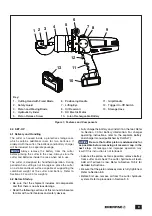
Key:
1. Positioning Handle
2. Lifting Eye
1
2
Figure 11, Positioning Handle and Lifting Eye
NOTICE:
WARNING
Because the cutter components are very
heavy, there is a risk of cuts, crushing or broken bones. To
avoid accidents, use care when working with the cutter.
Serious personal injury may result if the cutter is not
properly supported and handled in an appropriate way.
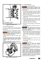
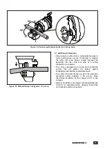
9.5 Positioning Material Inside the Cutting Head
Be sure that the piston and moving blade are located in
the fully retracted “home” position before placing any
material inside the cutting head. See Figure 8.
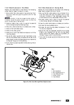
Position the material to be cut between the cutter
blades, so that it is perpendicular to the piston axis, as
shown in Figure 12. This will provide the best quality cut
while placing the least amount of load on the cutter.
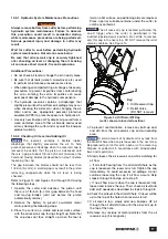
Adjust the support bolt as needed. The head of the
support bolt should just touch the surface of the material
to be cut, when the item is positioned against the fixed
blade of the cutter.
After adjusting the support bolt, be sure that the support
bolt retaining nut is snug tight against the support
bolt mounting ear. This will help prevent support bolt
movement during cutting.
NOTICE
Be certain that the hardness, tensile strength
and diameter of the material do not exceed any of the
stated maximum limits.
Refer to
Section 2.1
of this
manual for additional information. Failure to observe this
instruction may result in poor cutting performance
and/or damage to the cutter.
9.6 Cutting Procedure (typical)
1. Be certain that a battery is installed on the cutter and
that the battery has sufficient charge to complete the
cutting operation.
2. Be sure that the piston is in the “home” (fully retracted)
position. See Figure 8.
3. Be sure that the piston release screw is turned fully
clockwise. See Figure 9.
4. Place the material to be cut between the fixed and
moving blades. Refer to instructions in Section 9.5 for
additional information.
NOTICE
Position the item to be cut so that it is as
perpendicular as possible to the blades, as described in
Section 9.5. Positioning the material at an angle will
side-load the piston. Jamming and/or damage to the
cutter may result.
5. Be certain that hands, fingers or other body parts are
not inside the cutting head.
6. Press and hold the on-off trigger to start the motor
and begin cutting.
7. After cutting is completed, wait until the piston
reaches the end of its stroke and then release the
on-off trigger. Verify that the moving blade reverses
direction and moves fully into the “home” (fully
retracted) position.
Summary of Contents for EBC20B
Page 25: ...25 Notes...
Page 26: ...26 Notes...
Page 27: ...27 Notes...
Page 28: ...199 Gateway Ct Columbus WI 53925 USA www enerpac com Made in Italy WWW ENERPAC COM...