

10
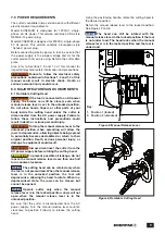
9.2 Operating Precautions
NOTICE:
WARNING
Failure to observe the following
precautions and instructions could result in death or
serious personal injury.
• Keep fingers, hands and other body parts clear of
the cutting head. Do not reach into the cutting area
during operation.
• Never place fingers, hands or other body parts
between objects being spread (such as a joint)
during the spreading process.
• When spreading, ensure that the spreading
wedges on the outside tips of the jaws fully engage
with the objects to be spread.
• Do not attempt to reposition the material being
cut while the tool is in operation. If repositioning is
required, stop the cutter.
• After cutting or spreading is complete, material
may fall. Keep body parts and equipment away
from area under and beside the cutter.
• Dangerous projectiles could occur at any
time during cutting. Always wear face and eye
protection. Keep persons away from cutting area.
• Cutter surfaces can become very hot. To prevent
burns, avoid contact with cutter components and
wear appropriate personal protective equipment.
• Refer to additional safety precautions in Section 1.0
of this manual before using the cutter or performing
any maintenance or repair activities.
9.3 Trapped Air Removal
Before placing a new cutter into operation, cycle the
piston several times without load to remove any trapped
air in the hydraulic circuit.
Air is completely purged when the piston advances and
retracts smoothly in both directions, from fully advanced
to fully retracted.
This procedure should be performed after the oil in the
cutter is changed, and after any maintenance or repair
activity in which the oil is drained and replaced.
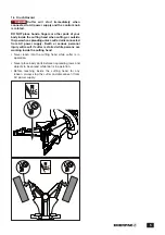
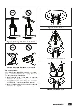
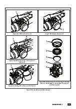
9.4 Positioning Material to be Cut
Position the material to be cut between the cutter blades
so that it is perpendicular to the blade axis, as shown in
Figure 4. This will provide the best quality cut.
Position the material at the base of the blades. Do not
position the material at the tips of the blades. See Figure 5.
NOTICE
Be certain that the properties of the material to
be cut do not exceed the stated maximum limits
applicable to your cutter model. Refer to Section 2.1 of
this manual for additional information. Failure to observe
the instruction may result in poor cutting performance
and/or damage to the cutter.
9.0 CUTTER OPERATION
9.1 Foreseen Use and Residual Risks
NOTICE:
WARNING
Failure to observe and comply with the
instructions and precautions contained in the
following paragraphs could result in death or serious
personal injury.
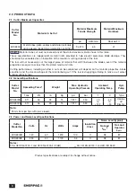
1. The ECSE-Series Cutter/Spreader must be used
only to cut metal tubes, plate, cables and similar
materials during decommissioning or demolition.
The tool may also be used to spread objects apart
for decommissioning, demolition or maintenance
purposes. When cutting, material specifications
must not exceed the allowable values shown in
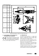
Section 2.1 of this manual. When spreading, observe
the rated spreading force indicated in Section 2.2, and
the spreading range indicated in Section 2.4 (item D).
2. The tool may be used only if powered by an electrical
system compliant with legislation and current law
(suitably connected to a grounded electrical system
and protected from current surges and short circuits).
3. Operators must observe the instructions in this
manual in order to minimize the risk of accidents. In
particular, operators must pay attention when working
in conditions that could cause:
• Possible burns from overheated metal parts.
• Injury due to incorrect positioning or inadequate lifting
or moving.
• Injury caused by splinters discharged from the
workpiece.
NOTICE:
WARNING
People remaining in the vicinity of the
tool while it is working are subject to the risk of flying
debris (dangerous objects, etc. ). Serious personal
injury could result.
4. Mechanical vibrations transmitted to the hands and
arms can pose a risk to the health and safety of
workers. The user and/or employer is responsible for
assessing the risk generated by mechanical vibrations
from the tool, and minimizing the possibility of injury.
5. Incorrect use:
• The tool must not be used for purposes other than
indicated in this manual.
• The tool must not be used in areas subject to the risk
of explosion.
Summary of Contents for ECSE300
Page 20: ...WWW ENERPAC COM...


