

14
10.5.3 Changing the Oil
NOTICE
The oil change procedure will replace most,
but not all, of the oil. It is to be performed for maintenance
purposes. If the oil is contaminated, or if for any other
reason a full oil evacuation is necessary, cylinder
disassembly by an Enerpac authorized service center is
required in addition to the standard oil change
procedure.
NOTICE
The oil change procedure is very detailed and
will take a considerable amount of time. It should only
be performed by a trained technician at an Enerpac
authorized service center. Failure to properly perform
the procedure may result in incomplete filling of the
cutter oil reservoir, which could lead to cavitation, air
entrainment, reduced performance and pump damage.
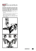
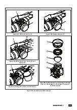
Change the oil in the cutter hydraulic reservoir as
described in the following steps. Refer to Figures 9A
through 9E:
1. Fill a clean oil dispenser with new Enerpac HF oil. Put
the dispenser aside for later use.
2. Fully close the jaws.
3. Disconnect the cutter from the AC power supply to
prevent accidental motor start-up during the following
steps.
4. Place the cutter in the horizontal position, on a
stable and level work surface, upside down with
the diaphragm cover facing upwards. Place a pan
or suitable container under the cutter to catch any
spilled oil.
5. To prevent contamination, remove any built-up dust
and dirt from the oil reservoir cap, diaphragm cover
and surrounding area.
NOTICE
A small amount of hydraulic oil leakage may
occur when the diaphragm cover is removed in the next
step. Be prepared to catch this oil in a pan or with a
clean rag. Dispose of spilled oil in accordance with all
applicable laws and regulations.
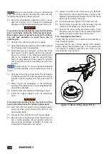
6. Remove the rubber support from the diaphragm
cover.
7. Using an adjustable face spanner wrench, loosen and
remove the diaphragm cover.
8. Remove the diaphragm from the diaphragm opening.
NOTICE
It is not necessary to remove the oil reservoir
cap, as the oil will be drained and filled through the
diaphragm opening.
9. Completely drain all old oil from the cutter through the
diaphragm opening, turning it right-side up and using
a suitable oil extraction system (used oil extraction
pump) if necessary, so that no oil remains in the
cutter reservoir.
NOTICE
Dispose of all used oil in accordance with all
applicable regulations and laws.
10.5.2 Checking Oil Level and Adding Oil
NOTICE
The reservoir contains a flexible rubber
diaphragm that slightly pressurizes the oil. To help
prevent excessive oil leakage when the reservoir cap is
removed, be certain that the piston is advanced as far as
possible and that the jaws are fully closed before
loosening the cap.
Refer to Figures 9A through 9C during the following steps:
1. Operate the cutter and fully close the jaws.
2. Disconnect the cutter from the AC power supply to
prevent accidental motor start-up during the following
steps.
3. Place the cutter in the horizontal position, on a stable
and level work surface, with the oil reservoir cap
facing upwards. Place a pan or suitable container
under the cutter to catch any spilled oil.
4. To prevent contamination, remove any built-up dust
and dirt from the oil reservoir cap and surrounding area.
NOTICE
A small amount of hydraulic oil may leak from
the drain/fill hole when cap is loosened in the next step.
Be prepared to catch this oil in a pan or with a clean rag.
Dispose of spilled oil in accordance with all applicable
laws and regulations.
5. Slowly loosen the oil reservoir cap while watching for
oil flow:
• If oil starts flowing from the oil drain/fill hole as the
cap is loosened, the reservoir is full. Tighten the cap
immediately. To avoid excessive oil spillage, do not
continue loosening the cap if oil flow occurs. Skip
steps 6 through 8 and go on to step 9.
• If no oil flow occurs when the cap is loosened,
fully loosen and remove the cap. Then, check
oil level and add oil (if needed) as described in
steps 6 through 8.
6. Check the oil level in the drain/fill hole. Oil level will be
up to the top of the hole when reservoir is full.
7. If oil level is low, slowly add new Enerpac HF oil
through the oil drain/fill hole, until the oil level is up to
the top of the hole.
8. Remove any residue or metal particles from the oil
reservoir cap (it is magnetic).
9. Install and securely tighten the oil reservoir cap.
10. Using a clean rag, wipe the cutter housing, grip and
motor so that these surfaces are free of oil residue.
11. Connect cutter to AC power supply. Cycle the
piston several times to test for proper operation
before placing the cutter back into service.
Summary of Contents for ECSE300
Page 20: ...WWW ENERPAC COM...


