background image

12

9.6  Cutting Procedure (typical)

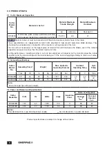
1. Be certain that the properties of the material to be cut 

do not exceed the stated maximum limits applicable 

to your cutter model. Refer to the chart in Section 2.1 

of this manual.

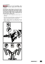
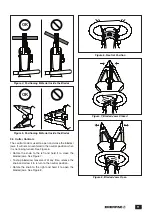
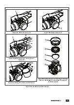
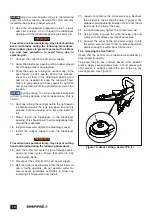
2. Place the material to be cut between the blades. 

Be sure that it is perpendicular to the blade axis, as 

shown in Figure 4. Refer to instructions in Section 9.4 

for additional information.


NOTICE

Failure to properly position the material in 

the blades may result in blade breakage and reduced 

cutting efficiency.

3. Connect the cutter to the electrical outlet.
4. Turn the control knob to the left and hold it until the 

item has been fully cut.

5. Turn the control knob to the right and release it to fully 

open the blades. The control knob will return to the 

neutral position.

9.7  Spreading Procedure (typical)

1. Turn the control knob to the left to close the jaws.
2. Place the jaws into the area between the two 

objects that are to be spread apart. Make sure the 

flat spreading wedges on the tips of the jaws are 

fully engaged with the objects to be spread, and 

properly positioned so they cannot slip out during the 

spreading process.


NOTICE:

  WARNING

Never place fingers, hands or other 

body parts between objects being spread (such as a 

joint) during the spreading process.


NOTICE:

  WARNING

After spreading is complete, material 

may fall. Keep body parts and equipment away from 

area under and beside the cutter.

3. Turn the control knob to the right to open the jaws and 

begin spreading.

4. Once the spreading is complete, turn the control knob 

to the left to close the jaws.

5. Remove the cutter from the objects being spread.

10.0  MAINTENANCE

10.1  Preparation for Maintenance

All cutter maintenance procedures must be performed 

under the following conditions:
•  Material must be removed from the cutting head.
•  The cutter must be disconnected from the AC power 

supply.

•  The cutter must be given time to cool to prevent burns.
•  Procedures must be performed in a suitable work 

environment in accordance with all current safety 

regulations and/or laws in your country or region.

•  The cutter must be cleaned thoroughly before 

maintenance procedures are performed.

•  Suitable personal protective equipment (PPE) must be 

used and/or worn while performing any work.


NOTICE:

  WARNING

The cutter must sometimes be 

operated in order to complete a maintenance or 

repair procedure being performed, or to prepare it 

for a procedure that is about to be performed.
However, to prevent start-up while persons are 

working on the cutter, always disconnect the cutter 

from the AC power supply before beginning any 

procedure steps that require use of tools and/or 

physical contact with the cutter. Failure to observe 

this precaution may result in death or serious 

personal injury.

Summary of Contents for ECSE300

Page 1: ...l are DANGER WARNING CAUTION and NOTICE NOTICE DANGER Indicates a hazardous situation that if not avoided will result in death or serious personal injury NOTICE WARNING Indicates a hazardous situation...

Page 2: ...clean and replace blades when they become dull Suitably maintained cutting tools with sharp edges are less likely to jam and are easier to control Keep this manual for future reference in a place that...

Page 3: ...nerpac HF hydraulic oil Use of any other oil may result in unsafe operation and or damage to tool The Enerpac product warranty may also be invalidated Keep hydraulic equipment away from flames and hea...

Page 4: ...l rating of the extension cord should be at least as great as the electrical rating of the tool 2 The extension cord should have a polarized plug at one end and a polarized receptacle at the other It...

Page 5: ...g unless cutter is disconnected from AC power supply Death or serious personal injury will result if cutter is started while persons are working inside the cutting head Never reach into the cutting he...

Page 6: ...f the material properties are equal to or less than the stated maximum limits Cutting performance including whether a cut can be completed will depend on the material properties blade condition and th...

Page 7: ...CSE300 is a rotatable head hydraulic cutter spreader used for cutting metal tubes plate cables and other similar materials during decommissioning or demolition activities The cutting head can be rotat...

Page 8: ...urface must be of sufficient capacity to support the weight of the cutter plus the additional weight of the material to be cut Refer to Section 2 2 for cutter weight 6 2 Before Start up Be sure that t...

Page 9: ...r to the unlocked position when spreading will allow the jaws to depressurize allowing objects being spread to potentially become destabilized or return to their original position Death serious person...

Page 10: ...rtain that the properties of the material to be cut do not exceed the stated maximum limits applicable to your cutter model Refer to Section 2 1 of this manual for additional information Failure to ob...

Page 11: ...d in the neutral position when it is not being turned See Figure 6 Rotate the knob to the left and hold it to close the blades jaws See Figure 7 To stop blade jaw movement at any time release the knob...

Page 12: ...process NOTICE WARNING After spreading is complete material may fall Keep body parts and equipment away from area under and beside the cutter 3 Turn the control knob to the right to open the jaws and...

Page 13: ...er exterior Refer to instructions in Section 10 3 Operator Check the tightening torque of screws and bolts Replace any missing screws or bolts Use torque wrench Refer to repair parts sheet for complet...

Page 14: ...mp if necessary so that no oil remains in the cutter reservoir NOTICE Dispose of all used oil in accordance with all applicable regulations and laws 10 5 2 Checking Oil Level and Adding Oil NOTICE The...

Page 15: ...Support 1 1 Figure 9B Oil Reservoir Cap Loosen 1 and Tighten 2 2 1 1 Figure 9C Adding Oil to Reservoir Fill Hole 1 1 2 3 4 5 Figure 9E Rubber Support 1 Diaphragm Housing Cover 2 Diaphragm 3 Diaphragm...

Page 16: ...ening This should result in some oil leakage from around the diaphragm 16 Install and securely tighten the diaphragm cover 17 Install the rubber support onto the diaphragm cover NOTICE WARNING To avoi...

Page 17: ...ic storage case in a clean and dry location accessible only to authorized personnel 11 2 Return to Use after storage Before using the cutter after an extended period of storage or inactivity perform t...

Page 18: ...des Replace blades if worn or damaged Service Center Motor brushes worn Replace motor brushes if worn less than 0 2 inch 5 mm long Service Center Commutator worn Replace rotor and commutator assembly...

Page 19: ...oil if low Operator Piston gasket worn Replace piston gasket Service Center Pump malfunction Repair or replace pump Service Center 2 Tool operates with insufficient force Max pressure valve open Clean...

Page 20: ...WWW ENERPAC COM...

Reviews: