


15
3. Disconnect the cutter from the AC power supply to
prevent accidental motor start-up during the following
steps.
4. Place the cutter in an upright position, on a stable and
level work surface, with the handle facing upwards.
Place a pan or suitable container under the cutter to
catch any spilled oil.
5. To prevent contamination, remove any built-up dust
and dirt from the oil reservoir cap, diaphragm cover,
and surrounding area.
NOTICE
When the handle is removed the wires from the
trigger on-off switch will still be connected to the electric
motor. Take care not to pull or stretch the wires when
removing the handle or when performing the oil change
procedure.
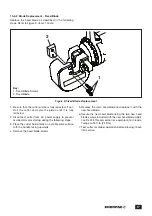
6. Remove the screws holding the tool handle in place.
Carefully remove the tool handle to gain access to the
diaphragm cover. The tool handle wiring will still be
connected, so use caution to avoid damaging this
wiring.
NOTICE
A small amount of hydraulic oil leakage may
occur when the diaphragm cover is removed in the next
step. Be prepared to catch this oil in a pan or with a
clean rag. Dispose of spilled oil in accordance with all
applicable laws and regulations.
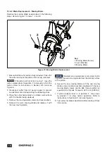
7. Remove the diaphragm cover by removing the six
screws securing it.
8. Remove the diaphragm from the diaphragm opening.
9. Completely drain all old oil from the cutter through the
diaphragm opening, turning it upside down and using
a suitable oil extraction system (used oil extraction
pump) if necessary, so that no oil remains in the cutter
reservoir.
NOTICE
Dispose of all used oil in accordance with all
applicable regulations and laws.
10. After all oil is evacuated, position the cutter with the
diaphragm opening facing up.
NOTICE
Use only new Enerpac HF oil in the following
step. Use of other oils may damage the cutter and may
invalidate the Enerpac product warranty.
11. Using the oil dispenser prepared in step 1, slowly
add new Enerpac HF oil through the diaphragm
opening until the diaphragm opening is nearly full.
NOTICE:
WARNING
To avoid serious personal injury, stay
clear of cutting head and blades during the following
procedures. Wear rubber gloves to prevent contact
with oil. Wear eye and face protection to avoid injury
due to splashing oil.
NOTICE:
WARNING
In the following steps, the tool must be
operated with the handle separated from the tool
housing. Use extreme caution to prevent injury as
service procedures are being performed.
12. Connect the cutter to the AC power supply.
13. Cover the diaphragm opening with a rubber-gloved
hand to help prevent oil splashing.
14. Prime the pump by pressing and releasing the
trigger in short bursts. During this process, check
the oil level in the diaphragm opening and add oil
(as needed) to keep the reservoir filled. Failure to
keep reservoir full may result in cavitation and
pump failure. Pump is primed when piston starts
extending.
NOTICE
During priming, the oil may become entrained
with air and may develop a foamy appearance. This is
normal.
15. Continue pressing and releasing the trigger in short
bursts as the piston extends. During this part of the
process, do not add oil, but verify that the pump has
ample oil supply. Continue until piston is extended
to approximately half stroke.
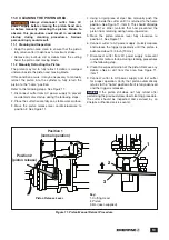
NOTICE
During the following steps, refer to Figure 5 for
piston release lever positions.
16. While covering the diaphragm opening with a
rubber-gloved hand, retract the piston gently by
slowly moving the piston release lever to position 2.
17. Move the piston release lever back to position 1 and
tighten.
18. Place the soft metal bar (refer to step 2) into the
cutting head.
19. Press and release the trigger in short bursts until
the piston is extended as far as possible, but before
it makes a full cut and retracts. The moving blade
will become lodged in the bar, preventing the
piston from retracting. This procedure is necessary
because the cutter mechanism alone may fail to
hold the piston in the partially extended position as
oil is being added in the following steps.
NOTICE
If you cut completely through the bar, try again,
cutting as far as you can without making a full cut.
20. Disconnect the cutter from the AC power supply
to prevent accidental motor start-up during the
following steps.
21. Add oil through the diaphragm opening until the
diaphragm opening is nearly full.
22. Slowly install the diaphragm in the diaphragm
opening. This should result in some oil leakage from
around the diaphragm.
23. Install the diaphragm cover and securely tighten the
six screws securing it.
24. Reinstall the tool handle. Be certain that electrical
wires are not pinched between tool housing and
handle.
25. Move the piston release lever to position 2 to retract
the piston. If piston is stuck, use the bar to manually
push the piston back until it retracts.
26. Remove the soft metal bar from the cutting head.
Do not discard the bar. It will be used again later in
this procedure.
Summary of Contents for EFBE5017
Page 23: ...Notes...
Page 24: ...WWW ENERPAC COM...


