background image

21

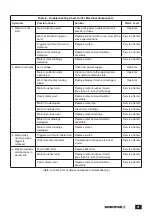
Table 2 - Troubleshooting Chart, Cutter Electrical Components

Symptom

Possible Cause

Solution

Maint. Level

1.  Motor will not 

start.

No AC electric power.

Check the power supply and circuit 

breaker or fuses.

Operator

Worn or broken AC power 

cord.

Replace old cord with a new cord of the 

same specifications.

Service Center

Trigger on-off switch worn or 

defective.

Replace switch.

Service Center

Motor rotor windings 

defective.

Replace rotor and commutator 

assembly.

Service Center

Motor stator windings 

defective.

Replace motor.

Service Center

2. Motor overheats. Low voltage.

Check AC power supply.

Operator

Motor ventilation slots 

obstructed.

Clean any dirt or other obstructions 

from motor ventilation slots.

Operator

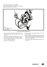
Worn fixed and/or moving 

blade.

Replace blades if worn or damaged.

Operator

Motor brushes worn.

Replace motor brushes if worn 

(less than 0.2 inch [5 mm] long).

Service Center

Commutator worn.

Replace rotor and commutator 

assembly.

Service Center

Motor fan damaged.

Replace motor fan.

Service Center

Motor windings dirty.

Clean dirty windings.

Service Center

Motor bearings worn.

Replace motor bearings.

Service Center

Motor rotor windings 

damaged.

Replace rotor and commutator 

assembly.

Service Center

Motor stator windings 

damaged.

Replace motor.

Service Center

3.  Motor does 

not stop when 

trigger is 

released.

Trigger on-off switch defective. Replace switch.

Service Center

Other electrical problem.

Troubleshoot and repair electrical 

circuit.

Service Center

4.   Electromagnetic 

disturbances in 

power line.

Fault in EMI filter.

Replace EMI filter.

Service Center

Motor brushes worn.

Replace motor brushes if worn 

(less than 0.2 inch [5 mm] long).

Service Center

Commutator worn.

Replace rotor and commutator 

assembly.

Service Center

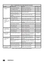
(Refer to Table 3 for hydraulic component troubleshooting.)

Summary of Contents for EFBE5017

Page 1: ...anual are DANGER WARNING CAUTION and NOTICE NOTICE DANGER Indicates a hazardous situation that if not avoided will result in death or serious personal injury NOTICE WARNING Indicates a hazardous situa...

Page 2: ...ep cutting tools clean and replace blades when they become dull Suitably maintained cutting tools with sharp edges are less likely to jam and are easier to control Keep this manual for future referenc...

Page 3: ...outlet or other electrical power source CAUTION Failure to observe and comply with the following precautions and instructions could result in minor or moderate personal injury Property damage could a...

Page 4: ...l rating of the extension cord should be at least as great as the electrical rating of the tool 2 The extension cord should have a polarized plug at one end and a polarized receptacle at the other It...

Page 5: ...dy inside the cutting head unless cutter is disconnected from AC power supply Death or serious personal injury will result if cutter is started while persons are working inside the cutting head Never...

Page 6: ...ximum limits is exceeded 2 2 General Specifications Cutter Model No Max Cutting Force Weight Max Hydraulic Operating Pressure Ambient Operating Temp Hyd Pump Tons kN lb Kg psi bar F C Type EFBE5017B 2...

Page 7: ...nd an internal hydraulic pump The pump provides oil flow to the hydraulic cylinder which advances the cylinder piston and moving blade A hydraulic reservoir with built in rubber diaphragm provides a c...

Page 8: ...and that there is no obvious damage Read the following sections of this manual to become familiar with cutter features and safety devices Verify that the AC power supply is of the correct specificati...

Page 9: ...dirt or debris is preventing its return NOTICE CAUTION To prevent possible oil leakage do not loosen the piston release lever more than one full turn counter clockwise NOTICE Refer to the procedures i...

Page 10: ...RATION 9 1 Foreseen Use and Residual Risks NOTICE WARNING Failure to observe and comply with the instructions and precautions contained in the following paragraphs could result in death or serious per...

Page 11: ...r is not properly supported and handled in an appropriate way 9 5 Positioning Material Inside the Cutting Head Be sure that the piston and moving blade are located in the fully retracted home position...

Page 12: ...The cutter must be disconnected from the AC power supply The cutter must be given time to cool to prevent burns Procedures must be performed in a suitable work environment in accordance with all curre...

Page 13: ...ween the jaws of the cutter without being cut through completely as the piston is extended to slightly less than maximum travel 10 5 1 Hydraulic System Maintenance Precautions NOTICE WARNING Always di...

Page 14: ...C Oil Reservoir Cap Loosen 1 and Tighten 2 2 1 Figure 8B Handle Screws 1 1 1 Figure 8D Adding Oil to Reservoir Fill Hole 1 3 2 1 4 5 Figure 8E Screws 1 Diaphragm Cover 2 Diaphragm 3 Diaphragm Opening...

Page 15: ...to prevent injury as service procedures are being performed 12 Connect the cutter to the AC power supply 13 Cover the diaphragm opening with a rubber gloved hand to help prevent oil splashing 14 Prim...

Page 16: ...ntil the cap is installed for the final time Failure to do so may result in air remaining in the reservoir This may require special consideration when the soft metal bar is used 30 Do not operate cutt...

Page 17: ...event accidental motor startup during the following steps 3 Place the cutter horizontally on a stable work surface with the handle facing upwards 4 Remove the fixed blade screws 5 Remove the worn fixe...

Page 18: ...the new moving blade 10 6 3 Blade Replacement Moving Blade Replace the moving blade as described in the following steps Refer to Figure 10 items 1 2 and 3 Figure 10 Moving Blade Replacement 1 3 2 NOT...

Page 19: ...leaning procedure the cutter should be inspected and serviced by an Enerpac authorized service center 11 0 CLEANING THE PISTON AREA NOTICE WARNING Always disconnect cutter from AC power supply before...

Page 20: ...ic storage case in a clean and dry location accessible only to authorized personnel 12 2 Return to Use after storage Before using the cutter after an extended period of storage or inactivity perform t...

Page 21: ...tor brushes worn Replace motor brushes if worn less than 0 2 inch 5 mm long Service Center Commutator worn Replace rotor and commutator assembly Service Center Motor fan damaged Replace motor fan Serv...

Page 22: ...gasket worn Replace piston gasket Service Center Pump malfunction Repair or replace pump Service Center 3 Tool performs with insufficient force Max pressure valve open Clean or replace max pressure v...

Page 23: ...Notes...

Page 24: ...WWW ENERPAC COM...

Reviews: