20
L4478_a
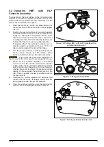
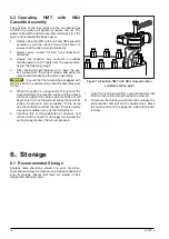
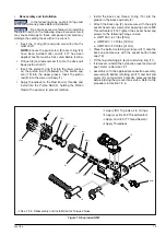
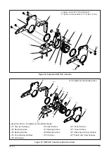
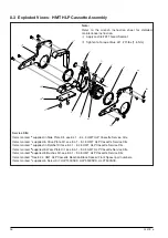
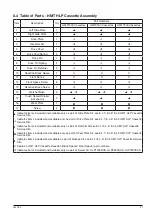
7.3.3 HMT HLP Cassette Assembly -
Disassemblyand Reassembly (Fig. 20/ 21)
• With the HLP cassette laid down on it side, remove
the three front spacer screws (12) and two reaction
block screws (13) followed by the one of HLP
cassette side plate (1 or 2).
• Separate the ratchet bush (14). The drive plate
assembly is free to be removed from the cassette.
Carefully remove the two compression springs (8)
from the drive plate and set to one side.
• Remove the ratchet (4), pawl (5) and pawl springs
(6).
• Disengage the two drive pin retainers (9), and slide
out the drive pin (7) from the drive plate
(3)
.
• On the remaining plate remove the three front
spacer screws (12) and two reaction block screws
(13) separate front spacer (11) and reaction block
(10) from the remaining HLP cassette side plate (1
or 2).
• Disassemble the reaction block by removing the
two socket head cap screws (17), and remove the
wear plate (16) from reaction block spacer (10).
• Clean all components with a mild solvent.
• Inspect all parts for damage. Any damaged
components must be replaced.
• Dry all components. Apply a thin coat of
molybdenum disulphide grease in the areas shown
in Figure 20.
Be sure that the ratchet, drive plate,
pawl, pawl spring, square drive, access plugs, and
compression springs are correctly installed, in the
reverse order of disassembly. Failure to install these
parts correctly will result in component damage. Refer
to figures 19 and 20.
• Assemble the HLP cassette assembly to the
appropriate drive unit body.
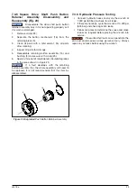
• Connect the wrench to the pump and perform
hydraulic pressure testing before placing the wrench
into service. Refer to the procedure in Section 7.2.6.
• Without the wrench on a nut or bolt, check
operation at a nominal pressure to make sure the
piston advances and retracts freely.
• Release the pressure and make sure that the piston
fully retracts.
NOTICE
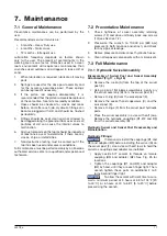
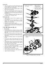
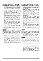
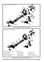
7.3.4 HMT HSQ Cassette Assembly -
Disassemblyand Reassembly (Fig. 22/ 23)
• To separate the square drive reaction arm (4),
unscrew the securing reaction arm grub screw (20)
and disengage.
• Remove the square drive circlip (8) and slide
the reaction arm spline (3) off the square drive
(2). Separate the drive bush (6) and remove the
remaining reaction arm circlip (9).
• Remove the square drive (2), drive retainer ring (21),
retainer block (5), and push button retainer (16).
• Remove the front spacer pins (22) followed by the
front spacer (15).
• The drive plate assembly is free to be removed
from the body. Carefully remove the two rod end
pin spring (18) from the drive plate and set to one
side.
• Disengage the two drive pin retainers (19), and
slide out the rod end pin (10) from the drive plate
(11)
.
• Remove the splined ratchet (7), pawl (
14
) and pawl
springs (13).
• If the linkpin (12) requires replacement, unscrew
the M4 button head screw (24) and separate link
pin and lanyard (23) from the body.
• Clean all components with a mild solvent.
• Inspect all parts for damage. Any damaged
components must be replaced.
Do not apply molybdenum disulphide
grease to the ratchet lever bore, or to the drive shoe
teeth. Application of grease to these areas will cause
erratic operation, slippage of drive mechanism and
excessive component wear.
• Dry all components. Apply a thin coat of
molybdenum disulphide grease in the areas shown
in Figure 22.
Be sure that the ratchet, drive plate,
pawl, pawl spring, square drive, access plugs, and
compression springs are correctly installed, in the
reverse order of disassembly. Ensure that the square
drive is inserted through the drive plate. Failure to install
these parts correctly will result in component damage.
Refer to figures 21 and 22.
• Assemble the Square Drive Cassette assembly to
the appropriate wrench body.
• Connect the wrench to the pump and perform
hydraulic pressure testing before placing the wrench
into service. Refer to the procedure in Section 7.2.6.
• Without the wrench on a nut or bolt, check
operation at a nominal pressure to make sure the
piston advances and retracts freely.
• Release the pressure and make sure that the piston
fully retracts.
NOTICE
NOTICE
Summary of Contents for HMT Series
Page 2: ......
Page 44: ...2020 Enerpac Tool Group All Rights Reserved www enerpac com...


