


2
2
3
4
9
10
5
6,
7
5
8
1
2.1 Hydraulic Nut Splitter Safety Precautions
WARNING:
Failure to observe the following precautions
may result in serious personal injury or death!
• Personal protective equipment must be worn at all times. Use
of safety footwear, thick gloves, overalls and safety glasses
is mandatory. These items are in addition to any other safety
equipment required at your site.
• Keep personnel clear while pressurizing the system. Allow
only relevant personnel to be within the work zone.
• Never exceed the maximum working pressure of the nut
splitter or any associated ancillary equipment. The maximum
working pressure of the nut splitter is 10,000 psi [700 bar].
• Do not place fi ngers or any part of the body between the nut
splitter and the nut. Keep hands clear of the nut splitter head
at all times and especially in the vicinity of the blade.
• Do not place fi ngers or hands underneath the body of the
nut splitter to support the weight, as hands or limbs could be
trapped when the pressure is applied.
• Lift the nut splitter using only the provided lifting eyebolt.
Always use appropriate lifting equipment. See Section 3.1 for
weights.
•
The nut splitter handle is provided for positioning and
maneuvering purposes only. Do not use the handle to carry the
nut splitter.
• Do not strike the nut splitter (or any of its components) with a
hammer or other objects in an attempt to shock or impact the
nut.
• Do not attempt to move or reposition the nut splitter while it
is in operation.
• Do not apply heat to the nut while the nut splitter is positioned
on the nut.
• When in operation, do not stand along the axis of the nut
splitter. Always stand to the side.
• Do not cut the nut into small pieces. Use a maximum of two
cuts. The second cut must always be at 180º (opposite) to the
fi rst.
• Hydraulic couplers are susceptible to knocks and damage.
Therefore, be careful when handling the equipment. A damaged
coupler or fi tting may burst or eject fl uid under pressure.
• Always allow the nut splitter cylinder to fully retract before
disconnecting hydraulic hose(s). High-pressure fl uid may be
ejected from an unretracted cylinder if a coupler has been
damaged during handling.
• Fully release hydraulic pressure and disconnect hydraulic
hose(s) from nut splitter cylinder before applying lubricant to
blade or performing any other work inside the cutting zone.
• Be careful when handling severed nuts. Sharp edges can
cause lacerations.
• Always use the correct size cutting head for the nut to be
cut.
• Do not insert packing pieces or shims behind the nut or
blade in an attempt to split a nut that is not within the specifi ed
size range for the cutting head.
• Use the nut splitter to cut hexagonal nuts only. Do not attempt
to cut square, round, bi-hex or 12-point nuts.
• Do not use the nut splitter to cut chains or bolts.
• Do not use the nut splitter to rotate nuts.
• Do not use the nut splitter's hydraulic cylinder for jacking,
lifting, pushing or any other purpose than that for which it is
intended.
• Sparks can be emitted at the blade tip when the nut fractures.
To minimize the risk of sparks or hot metal fragments, a water
spray can be directed over the entire nut and blade area.
However if there is any doubt as to whether sparks can be
effectively arrested, then the nut splitter should not be used.
• Never attempt to disconnect or retighten any part of the
hydraulic system while under pressure. Be sure pressure
gauge indicates zero (0) psi/bar before attempting to connect,
disconnect or tighten hydraulic fi ttings.
• Treat hydraulic hoses with care. Do not kink, twist or sharply
bend any hydraulic hose. Never exceed the hose manufacturer's
specifi ed minimum bend radius. Never use a damaged, worn
or split hose.
• Read and understand the operating instructions, maintenance
instructions and safety precautions contained in this instruction
sheet.
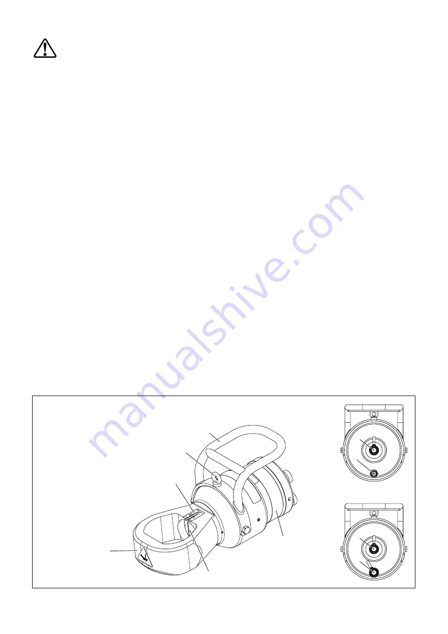
Figure 1, Features and Components, NS Series Nut Splitter
(rear view)
Single
Acting
Models
Double
Acting
Models
1. Cutting Head
2. Blade Cutting Depth Scale
3. Lifting Eyebolt
4. Handle
5. Hydraulic Coupler
6. Vent Plug
(single acting NS70 models only)
7. Pipe Plug
(single acting NS110 models only)
8. Hydraulic Coupler
(double acting models only)
9. Hydraulic Cylinder
10. Cutting Blade


