


4
5.0 ASSEMBLY
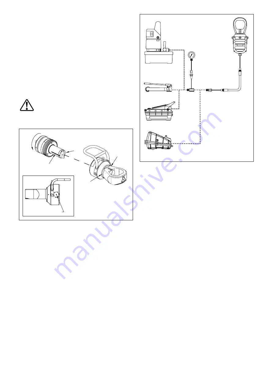
5.1 Assembling Cutting Head and Cylinder
The cutting head is shipped disassembled from the cylinder.
Assemble as described in the following steps:
1. Be sure that cylinder is fully retracted and disconnected
from the hydraulic pump.
2. Loosen the plastic set screw (Figure 3, item A) located on
the cutting head barrel.
3. Insert the cylinder into the head, aligning the axial slots
in the blade holder (Figure 3, item B) with the spring pins
(Figure 3, item C) in the cutting head bore. Once aligned,
rotate the cylinder in the direction shown in order to engage
the screw threads.
4. Continue rotating the cylinder until NO threads are visible on
the outside of the cylinder body (threads fully engaged).
WARNING:
Never use the nut splitter if any of the
cylinder threads are visible.
5. Install the cutting blade. Refer to Section 7.0 for installation
instructions.
B
A - Set Screw
B - Grooves
C - Spring Pins (inside bore)
C
B
C
A
Figure 3, Assembling the Cylinder and Cutting Head
5.2 Hydraulic Pump
A 10,000 psi [700 bar] hydraulic pump is required to operate
the nut splitter.
If a single acting nut splitter is used, the pump must be
equipped with a pressure release valve. If a double acting nut
splitter is used, the pump must be equipped with a suitable
4-way 3-position directional control valve.
Always check the pump hydraulic relief valve setting before
connecting the nut splitter. Maximum pressure must not exceed
10,000 psi [700 bar].
If an air-powered hydraulic pump is used, an air regulator must
be installed in the air supply line, limiting the air pressure to the
recommended range for the pump being used.
If the pump is not equipped with a hydraulic pressure gauge,
install a 0-10,000 psi [0-700 bar] gauge between the pump
outlet and the hydraulic hose.
5.3 Hose Connections
Be sure to use only high pressure hoses and fi ttings designed
for 10,000 psi [700 bar] operation. See Figure 4 for typical
pump and hose arrangements.
Single acting nut splitters are equipped with
one
Enerpac
CR-400 3/8" female coupler. Double acting nut splitters are
equipped with
two
Enerpac CR-400 3/8" female couplers.
Figure 4, Hydraulic Connections (typical pumps shown)
Connect the hydraulic hose(s) between the pump and the nut
splitter cylinder. Check that couplers on both ends of hose(s)
are fully screwed together. Firmly tighten couplers by hand to
prevent restricted oil fl ow.
IMPORTANT:
Be sure that all couplers are fully connected.
Loose or partially connected couplers will block the fl ow of oil
between the pump and the nut splitter.
To remove any air trapped in the system, advance and retract
the cylinder several times.
6.0 OPERATION
6.1 Adjusting Blade Cutting Depth
(If bolt diameter is shown on the scale)
The blade cutting depth scale allows the user to set the nut
splitter's maximum stroke, and the corresponding depth of
the cutting blade. This feature helps prevent bolt damage from
occurring due to excessive blade penetration.
Adjust the cutting depth as described in the following steps:
1. Ensure that the nut splitter cylinder is fully retracted.
2. Check that the bolt diameter is within the range of the
cutting head to be used (bolt diameter range is indicated
on the scale). See Section 3.2 for additional information.
Note:
The cutting depth scale is calibrated only for the following
thread, bolt and nut types:
Imperial threads
- Unifi ed (UN) bolt threads with heavy series
nuts.
Metric threads
- Metric (M) bolt threads with standard series
nuts.
If any other thread, bolt or nut type is present, skip the following
steps in this section and refer to Section 6.2 for additional
instructions.
Enerpac PU Series
Electric Pump
Enerpac P Series
Hand Pump
Enerpac PA Series
Air-Hydraulic Pump
Enerpac XA Series
Hydraulic Pump
0-10,000 psi
[0-700 bar]
Pressure Gauge
Note:
Hose arrangement for
single acting nut splitter
models is shown.
Double acting nut splitter
models require TWO
hoses, one for
extend
and one for
retract
.


