© 2015 Enerpac, All Rights Reserved
7
PTW Series Pneumatic Torque Wrench
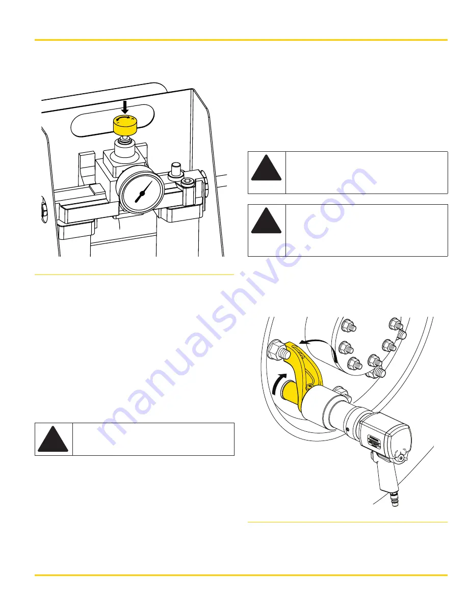
2. The torque output of the tool is set by adjusting
the air pressure using the regulator on the FRL.
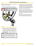
Fig. 7
3. Determine the correct air pressure for the desired
torque setting by using the chart from the most
recent calibration. A factory calibration chart is
provided by Enerpac in the tool case.
4. Adjust the lever on the back of the tool indicated
in Fig. 6 so the tool is set to the highest speed
and direction of rotation.
The tool calibration chart provided by Enerpac for
this tool was produced with the tool on the highest
speed. Tool performance in this speed will most
closely reproduce the pressure/torque ratio listed in
this chart.
!
WARNING: Do not attempt to operate
the tool at pressures exceeding the
torque ratings from the supplied chart.
NOTE:
For an accurate torque value, the air pressure
must be adjusted with the tool free-running (rotating
freely, not under load).
5. Fully depress the trigger of the tool and adjust
the regulator to the correct pressure while the
tool is free-running.
6. Make sure the appropriate reaction arm is
installed onto the tool.
7. Determine the correct size socket and install it
on the square drive. It is recommended that the
socket be pinned onto the square drive.
8. Install the socket onto the fastener and rotate the
body so the reaction arm is positioned against
the reaction point.
!
WARNING: To prevent serious
crushing injury, always keep all body
parts away from the reaction point
when the tool is in use.
!
CAUTION: When in operation, the
reaction arm rotates in the opposite
direction of the square drive. Always
make sure the reaction arm is
positioned against a solid fixed object.
NOTE:
For clockwise rotation, the adjustment lever is
set to the “F” position.
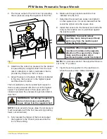
9. Fig. 8 shows the position for the reaction arm
when the square drive rotates clockwise.
Fig. 8


