background image

L4627_b

3

1.  Safety

1.1  Safety Precautions 

Failure to observe and comply with the following 

precautions could result in death or serious personal 

injury. Property damage could also occur.

•  Read and completely understand the safety 

precautions and instructions in this manual before 

operating the SHS or preparing it for use. Always 

follow all safety precautions and instructions, 

including those that are contained within the 

procedures of this manual.

•  Always wear protective head-wear, ear protectors, 

footwear and gloves (at a minimum rigger type 

gloves) suitable for safe operation of the tool. 

The protective clothing must not interfere with 

safe operation of the tool or restrict the ability to 

communicate with co-workers.

•  Be sure your workplace is safe. Follow the 

instructions in your workplace’s standard 

operating procedures and be sure to observe all 

communicated safety precautions.

•  Ensure all hydraulic components are rated to a safe 

working pressure of 700 bar (10150 psi).

•  Do not remove or disable the pump relief valve.
•  The system operating pressure must not exceed 

the pressure rating of the lowest rated component 

in the system.

•  Never set a relief valve to a higher pressure than 

the maximum rated pressure of the SHS. If ratings 

are different, relief valve setting should not exceed 

the setting of the lowest rated component (pump 

or cylinder).

•  Do not overload equipment. Never attempt to move 

a load with higher weight than the maximum load 

value of the SHS. Overloading causes equipment 

failure and possible personal injury.

•  Always perform a visual inspection of the SHS 

before placing it into operation. If any problems are 

found, do not use the cylinder. Have the cylinder 

repaired and tested before it is returned to service.

•  Never use a cylinder that is leaking oil. Do not use 

the SHS if is damaged, altered or in need of repair.

•  Always lift the cylinder using a crane or other 

suitable lifting device of sufficient rated capacity. 

Use only the 4 hoisting eyes on the SHS frame to 

attach the cylinder to the lifting device.

•  Allow only trained and experienced personnel 

to supervise and perform lifting and lowering 

procedures.

•  Be sure the operator has completed safety induction 

training, specific to the work surroundings. The 

operator should be thoroughly familiar with the 

controls and the proper use of the tool.

•  Be certain that no persons are working on or near 

the SHS before moving of the load begins. Alert all 

personnel in advance that the procedure is about 

to occur. 

  WARNING

Read all instructions carefully. Follow all recommended 

safety precautions to avoid personal injury as well 

as damage to the product and / or damage to other 

property. Enerpac cannot be responsible for any 

damage or injury from unsafe use, lack of maintenance, 

or incorrect operation. Do not remove warning labels, 

tags, or decals. In the event that any questions or 

concerns arise, contact Enerpac or a local Enerpac 

distributor for clarification.
Save these instructions for future use.
If you have never been trained on high-pressure 

hydraulic safety, consult your distributor or service 

center for information about Enerpac Hydraulic Safety 

Courses.
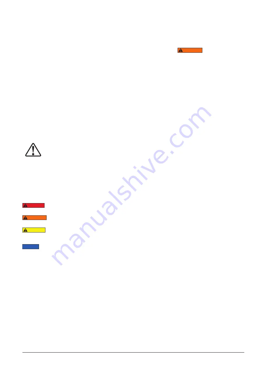
This manual follows a system of safety alert symbols, 

signals, words, and safety messages to warn the user of 

specific hazards. Failure to comply with these warnings 

could result in death or serious personal injury, as well 

as damage to the equipment or other property.

The Safety Alert Symbol appears throughout 

this manual. It is used to alert you to potential 

physical injury hazards. Pay close attention 

to Safety Alert Symbols and obey all safety 

messages


that follow this symbol to avoid the possibility 

of death or serious injury.
Safety Alert Symbols are used in conjunction with certain 

Signal Words that call attention to safety messages or 

property damage messages and designate a degree or 

level of hazard seriousness. The Signal Words used in 

this manual are DANGER, WARNING, CAUTION, and 

NOTICE.

Indicates a hazardous situation that, if not 

avoided, will result in death or serious personal injury.

Indicates a hazardous situation that, if not 

avoided, could result in death or serious personal injury.

Indicates a hazardous situation that, if not 

avoided, could result in minor or moderate personal 

injury.

Indicates information considered 

important, but not hazard related (e.g. messages related 

to property damage). Please note that the Safety Alert 

Symbol will not be used with the signal word.


DANGER

  WARNING

  CAUTION


NOTICE

Summary of Contents for SHC11020

Page 1: ...ent Revision B Document Revision Date FEB 2022 Document Language ENGLISH EN Operation and Maintenance Manual Manual Synchoist System Enerpac SHS To reduce the risk of injury user must read and understand this document before use ...

Page 2: ......

Page 3: ...precision matters elite professionals in industries such as aerospace infrastructure manufacturing mining oil gas and power generation rely on Enerpac for quality tools services and solutions For additional information visit www enerpac com WARRANTY Refer to the Enerpac Global Warranty document for terms and conditions of the product warranty Such warranty information can be found at www enerpac c...

Page 4: ...TALLATION 13 6 1 HANDLING 13 6 2 HYDRAULIC OIL REQUIREMENTS 13 6 3 HYDRAULIC CONNECTIONS 13 6 4 ELECTRICAL CONNECTIONS 14 7 SCREENS 14 7 1 MAIN SCREEN 14 7 2 PARAMETERS SCREEN 15 8 OPERATION 15 8 1 PREPARING THE SYNCHOIST 15 8 2 MANUAL SHS HPU OPERATION 16 9 MAINTENANCE INSPECTION 16 9 1 MODIFICATIONS 16 9 2 SAFETY DURING MAINTENANCE 16 9 3 RESPONSIBILITIES 17 9 4 GENERAL MAINTENANCE PROCEDURE 17 ...

Page 5: ...ocedures Besuretheoperatorhascompletedsafetyinduction training specific to the work surroundings The operator should be thoroughly familiar with the controls and the proper use of the tool Be certain that no persons are working on or near the SHS before moving of the load begins Alert all personnel in advance that the procedure is about to occur WARNING Read all instructions carefully Follow all r...

Page 6: ...chine parts sharp edges weld spatter corrosive chemicals and excessive heat or flame Do not drop heavy objects on hoses A sharp impact may cause internal damage to hose wire strands Applying pressure to a damaged hose may cause it to rupture Keep hydraulic equipment away from flames and heat Excessive heat will soften packings and seals resulting in fluid leaks Heat also weakens hose materials and...

Page 7: ...is compatible to all CE Requirements A copy of an EU Declaration of Conformity is enclosed with each shipment of this product These tools conform with the requirements for CE and UKCA SHS45520MW SHS45540MW SHS45560MW SHS48520MW SHS48540MW SHS48560MW SHS411040MW SHS411060MW SHS45520MJ SHS45540MJ SHS45560MJ SHS48520MJ SHS48540MJ SHS48560MJ SHS411040MJ SHS411060MJ ...

Page 8: ...distance The equipment must be transported in a frame designed for this purpose This frame can be placed in a container to provide good protection against weather influences and give a good rigid protection Make sure that all parts are secured against sliding around Refer to Figure 1 for frame details Figure 1 SHS transport frame parts 1 Frame Support 2 Synchoists Support 3 Eyebolt Place the synch...

Page 9: ...rame assembly CONNECTION BOLT SUPPORT HOLE SUPPORT NARRROWING SYNCHOIST ATTACHMENT in the vertical position 2 Connect the rear clevis eye with a shackle to hold the synchoist 3 Lower and displace the synchoist to release the conection bolts from the synchoist support 4 Lift the synchoist and remove it from the transport frame to start working operation SHACKLE CONNECTION FRAME DISASSEMBLE SYNCHOIS...

Page 10: ...rn Filter 7 Gauges 3 Control Lever 8 Visual Level 4 Electric Plug 9 Breather Filter 5 Motor Starter 10 Manifold Assembly Figure 5 Features and components of Manual SHS HPU In W models Pressure Reading Device PRD is optional and it is not included on the package while in J models PRD is factory mounted ...

Page 11: ...4 2 Synchoist Cylinders 1 Protector Assembly 6 Connection Bolt 2 Manifold Assembly 7 Plunger 3 Lifting Eyes 8 Sensor Connection Port 4 Cylinder Body 5 Clevis Eye Figure 6 Features and components of SHS Cylinders ...

Page 12: ... 4 x 0 36 gal min 4 x 1 68 l min 4 x 0 44 gal min 4 x 2 1 l min 4 x 0 55 gal min 4 x 2 52 l min 4 x 0 66 gal min Max Pressure 700 bar 10150 psi 700 bar 10150 psi 700 bar 10150 psi 700 bar 10150 psi Reservoir 250 l 66 04 gal 250 l 66 04 gal 250 l 66 04 gal 250 l 66 04 gal Wet Weight 695 kg 1532 21 lbs 695 kg 1532 21 lbs 725 kg 1598 35 lbs 725 kg 1598 35 lbs Motor Power 7 5 kW 9 kW 11kW 13 2 kW Moto...

Page 13: ...4 200 7 87 500 19 68 315 12 40 205 8 07 SHC11060 780 30 70 174 6 85 405 15 94 200 7 87 500 19 68 315 12 40 205 8 07 Model H I J K L M mm in mm in mm in mm in mm in mm in SHC5520 59 2 32 1300 51 18 80 3 14 91 5 36 02 91 5 36 02 80 3 14 SHC5540 59 2 32 1800 70 86 80 3 14 91 5 36 02 91 5 36 02 80 3 14 SHC5560 59 2 32 2300 90 55 80 3 14 91 5 36 02 91 5 36 02 80 3 14 SHC8520 72 2 83 1330 52 36 100 3 93...

Page 14: ...11060 110 Ton Cylinder Characteristics Pushing Pressure 125 bar 1812 psi Pushing Capacity 36 1 Ton 354 02 kN Pulling Pressure 700 bar 10150 psi Pulling Capacity 114 8 Ton 1125 8 kN External Diameter 315 mm 12 40 in Internal Diameter 190 mm 7 48 in Plunger Diameter 125 mm 4 92 in Effec Area Pushing 283 5 cm2 439 42 in2 Effec Area Pulling 160 8 cm2 249 24 in2 Area Ratio 1 76 Model SHC11020 SHC11040 ...

Page 15: ...n using a hand operated pump to power the cylinder s it is permissible to use a high quality brand of ISO 15 hydraulic oil The lower oil viscosity will result in reduced pumping effort especially in cold weather conditions 6 3 Hydraulic Connections CAUTION On double acting cylinders be certain that hoses are connected to BOTH couplers Never attempt to pressurize a double acting cylinder if only on...

Page 16: ...corner button is pushed the user will enter the Parameters screen Figure 10 Hoses connection layout CAUTION Extend and retract the piston rods a few centimeters before installing the cylinders under the hook Enerpac recomends this to be done while cylinders are located in the transport structure Check all cylinders for leakage 6 4 Electrical Connections The pump is factory equipped with a 3 phase ...

Page 17: ...an The system will show the maximum capacity of the pressure transducer 6 Maximum Total Load The user must type the maximum load expected of all cylinders which are involved in the current application When this value is exceeded the control will show a warning alarm and the movement will be stopped 8 Operation 8 1 Preparing the Synchoist Synchoist cylinders must be positioned vertically hanging on...

Page 18: ...ssary to keep SHS in good operating condition at all times The early recognition and elimination of minor irregularities and immediate replacement of worn and damaged parts will help prevent downtime associated costs and safety issues 9 1 Modifications Perform the prescribed maintenance tasks at the prescribed times and observe the details regarding the replacement of components If modifications t...

Page 19: ...sponsibility to maintain the system regularly for durability and to keep it in good working conditions 9 4 General Maintenance Procedure Before during and after maintenance the following procedures are applicable 1 Procedures prior to maintenance work Let powerpacks cool down When working on the electrical system or welding on the work site shut down the powerpack and remove all electric connector...

Page 20: ...18 L4627_b 10 Hydraulic Schemes 10 1SHP414MW 10 2SHP414MJ 10 3SHP421MW ...

Page 21: ...L4627_b 19 10 4SHP421MJ 10 5 SHC Distribution Block with Pressure Transducers ...

Page 22: ...2 4 Hinge Bolt M8 10 DB130202 5 Flat Washer 10 50 x 20 x 2 6 CAE1100108 1A 6 SHP Reservoir 1 DDB0127025 7 Acorn Nut M10 6 CAE1100055 1A 8 Reservoir Register Plate 1 DB9091900 9 Ball Valve Assembly 1 DB9359900 12 10 Visual Level FSA 2 DB4405022 11 Lifting Eyes M8 4 CBB1080120 1D 12 Manual SHS Top Cover Plate 1 DB0125201 9 13 SHS Frame 1 DB0125201 14 Manual SHS Top Cover Door 1 DB0125201 10 99 15 SH...

Page 23: ...P421MJ 1 Electric Motor 1 DB4348259 DB4431259 DB4621259 DB4432259 2 1 Return Filter Housing 1 DB4603118 2 2 Return Filter Element 1 DB4604175 2 3 Clogging Filter Indicator 1 DB4605118 3 Gauge 700 bar 4 G2538R 4 Pressure Reading Device 1 SHS PRD SHS PRD 5 Motor Starter 1 DB06914380 6 Electric Plug 1 DB06447606 7 Breather Filter 1 DB4368118 8 Manual SHS Manifold Assembly 1 DB9206900 ...

Page 24: ... Description Qty Part Number 1 Manifold 1 DB5086840A 2 Relief Valve 4 DB1062663 3 Hand Directional Valve 4 3 700 bar 4 DB1154661 4 Relief Valve 4 DB1062663 1 5 Male Coupler 4 CH604 6 Female Coupler 4 CR400 7 Fitting 4 FZ1617 8 1 16 NPT Plug 12 A1006245 9 1 8 BSP Plug 4 DB2142006 10 1 2 BSP Plug 1 DB2141006 11 Test Point Minimess 1 4 BSP 680 bar 4 DB2421034 ...

Page 25: ... Part 6 Rod 1 Not Available as Service Part 7 Stroke Sensor 1 Not Available as Service Part 8 Protector Assembly 1 Not Available as Service Part 9 Clevis Eye 1 Not Available as Service Part 10 Screw Din 913 M8 x 20 3 CCA821028 5A 11 Flush Plug 1 4 2 A1008245 12 Separator 1 DB80006101 13 Magnet 1 DB8009384 14 Synchoist Cylinder Safety Block w sensor 1 DB9346900 Synchoist Cylinder Safety Block no se...

Page 26: ...s Service Part 31 Screw Din 913 2 Not Available as Service Part 32 Identification Plate 1 B140090026 20 33 Allen Bolt Din 912 M3x9 4 CBA311028 1A 34 Allen Bolt M6 x 16 6 DB016028 1A 35 O Ring 1 Not Available as Service Part 36 O Ring 1 Not Available as Service Part 37 Back Up Ring 1 Not Available as Service Part 38 Screw SHC M24 x 50 2 DB9482242 Notes Parts pointed with this mark are only availabl...

Page 27: ...e alarm chart is not all inclusive and should be only considered as an aid to help diagnose the most common problems For repair service contact Authorized Enerpac Service Center ALARMS CHART ALARM POSSIBLE CAUSE SOLUTION Cylinder Pressure Signal Failure The pressure transducer signal of indicated cylinder is not reaching the PLC Visually check the pressure transducer and the cable Reset alarm Maxi...

Page 28: ..._________________ ____________________________________________________________________________________ ____________________________________________________________________________________ ____________________________________________________________________________________ ____________________________________________________________________________________ __________________________________________...

Page 29: ..._________________ ____________________________________________________________________________________ ____________________________________________________________________________________ ____________________________________________________________________________________ ____________________________________________________________________________________ __________________________________________...

Page 30: ..._________________ ____________________________________________________________________________________ ____________________________________________________________________________________ ____________________________________________________________________________________ ____________________________________________________________________________________ __________________________________________...

Page 31: ..._________________ ____________________________________________________________________________________ ____________________________________________________________________________________ ____________________________________________________________________________________ ____________________________________________________________________________________ __________________________________________...

Page 32: ... 2022 Enerpac Tool Group All Rights Reserved www enerpac com ...

Reviews: