L4555_a
19
7. Tighten the locknut when the desired pressure
setting is reached.
8. Shift the control valve so that the system pressure
returns to 0 psi/bar.
9. Shift the control valve again and repressurize the
system. Observe the pressure gauge and verify that
the setting is correct.
10. Fully relieve hydraulic pressure before removing
gauge and plug (if installed in step 2) from ports.
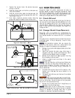
Figure 14: Relief Valve - VM22
Relief valve body|
(DO NOT TURN)
Set screw
Locknut
“A”
Port
Figure 15: Relief Valve - VM32
Relief valve body
(DO NOT TURN)
Set screw
Locknut
“A”
Port
Figure 16: Relief Valve - VM, VE and VEW 33 & 43 Series
Relief valve body (DO NOT TURN)
Set screw
Locknut
“A”
Port
“B”
Port
(not present
on all models)
9.0 MAINTENANCE
Frequently inspect all system components for leaks or
damage. Repair or replace damaged components. Note
that electrical components, for example, the power cord,
may only be repaired or replaced by a qualified electrician,
adhering to all applicable local and national codes.
9.1 Check Oil Level
Check the reservoir oil level prior to start-up. If oil level is
low, remove the oil fill plug and add additional oil to the
reservoir as needed. Always be sure cylinders are fully
retracted before adding oil to the reservoir. See Figure 2
earlier in this manual for oil level diagram. See Figure 3 for
fill plug location.
9.2 Change Oil and Clean Reservoir
Frequently check oil condition for contamination by
comparing the color of the oil in the pump reservoir to
new unused Enerpac oil. Enerpac HF oil is a crisp blue
color.
As a general rule, completely drain and clean the reservoir
every 250 hours, or more frequently if used in dirty
environments.
NOTICE
This procedure requires that you remove the
pump from the reservoir. Work on a clean bench and
dispose of used oil according to local regulations.
1. Remove the reservoir drain plug and drain all oil from
the reservoir.
2. Clean and reinstall the drain plug. Drain plug is
magnetic and may contain metal particles which
must be removed before plug is reinstalled.
3. Remove the 13 bolts and copper gaskets securing
the coverplate to the reservoir.
4. Attach a suitable hoist and slings to the pump
carrying handle.
NOTICE
In the next step, be sure the pump is lifted evenly
and does not drop. As the pump is being lifted, have a
second person separate the pump coverplate from the
mating surface of the reservoir using a screwdriver or
other suitable tool.
5. Carefully lift the pump unit out of the reservoir. Use
caution not to damage the pump element or oil
intake filter.
6. Thoroughly clean the reservoir interior with a suitable
cleaning agent.
WARNING
When using cleaning agents and solvents,
always read, understand and follow manufacturer’s safety
and use instructions. Failure to observe this precaution
may result in serious personal injury.
7. Remove the oil intake filter. Pull it straight down to
separate it from the intake tube.
NOTICE
Replacement of the oil intake filter is strongly
recommended whenever the reservoir interior is cleaned.
However, if desired, an existing intake filter in good
condition can be back flushed and reinstalled.


