background image

Enersol Pool Panel Installation Guide                    


11 | 

P a g e


6 - SYSTEM REGULATION 
OPTIONS (continued)


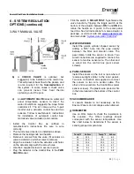
3-WAY MANUAL VALVE  


b)  

CHECK 

VALVE 

is 

optional, 

but 

suggested, to be installed on the return line. 
This will prevent back flow to the panels, and 
is  also  required  for  the 

Summerization

  of 

the  system.  In  some  cases  a  check  valve 
can  prevent  losses  from  heat  thermo 
siphoning out of the pool. 

c)  

An 

AUTOMATIC VALVE

 relies on water and 

panel  temperature  sensors  to  divert  the 
water.  EnerWorks  suggests  the  Aqua  Solar 
controller  kit.  The  kit  comes  with  a  3-port 
diverter  valve,  actuator,  control box  and  two 
sensors.  Follow  manufacturer’s  instructions 
for  installation  of  automatic  control  box, 
motorized valve (actuator) and controls.  


•  Install  the  Control  Box  as  outlined  in 

manufacturer’s  instructions.  Be  sure  to  wire 
correctly.  

•  The 3-port valve (diverter) is installed as above.  
•  Remove the locking knob and handle.  
•  Remove 4 screws from  the valve (fit actuator on 

valve to determine which screws to remove).  

•  Align  the  actuator;  rotate the  actuator  until  holes 

on the actuator align with the screw holes.  

•  Use the 4 supplied screws to secure in place.  
•  Plug the actuator in the Control Box in the 

FWD 

VALVE 

socket.  


•  Flick the switch to 

SOLAR TEST

. Synchronize the 

valve  handle  by  flipping  the  toggle  switch  at  the 
bottom of the actuator between 

ON 1 

and 

ON 2 

to 

rotate  the  handle  so  it  points  to  the  solar  panel 
feed line. See full instructions for valve actuator in 
package, or visit our web site, 

www.enersol.com


and look under “

System Automatic Controller

”. 


d) WATER SENSOR 


Install  the  plastic  cylinder  shaped  sensor  by 
drilling  a  5/16”  hole  into  the  pipe  usually 
between  the  filter  and  diverter  valve.  The 
gear  clamp  holds  the  sensor  in  place.  Two 
wired connectors are supplied to connect the 
sensor to two line sensor wire. The other end 
is  wired  into  the  control  box  (pool  sensor 
screws).  

e) PANEL SENSOR 


Install the sensor on the roof or rack where it 
receives  sunlight  similar  to  the  solar  panels. 
Two wire connectors are supplied to connect 
the  sensor  to  two  wire  sensor  cable.  The 
other end is wired into the Control Box (solar 
sensor screws). The plastic wire protector fits 
in the hole located in the bottom of the control 
box.  

f) VACUUM BREAKER 


A  vacuum  breaker  is  not  necessary,  as  the 
Enersol Panels do not collapse when drained.  


g) OHM-METER 

Use  an  Ohm  meter  to  check  the  resistance  in 
the  sensors.  The  Ohms  readings  should 
correspond  with  the  sensor  temperature.  Use 
the  chart  below  to  determine  if  the  sensor  is 
sensing proper temperatures.  


Temp °F 

Kohms 


Temp °F 

Kohms 

65 

13.5 


95 

6.5 

70 

11.9 


100 

5.8 

75 

10.5 


105 

5.2 

80 

9.3 


110 

4.7 

85 

8.2 


115 

4.2 

90 

7.3 


120 

3.8 


Summary of Contents for Pool Panel

Page 1: ...1 800 884 6444 www enersol com April 2013 2013 Enerworks...

Page 2: ...Enersol Pool Panel Installation Guide 2 P a g e...

Page 3: ...and sales representatives of the Enersol solar products are in no way responsible if safety procedures installation instructions and common sense are not followed or if EnerWorks is not consulted sho...

Page 4: ...for assistance at 1 800 884 6444 c Measure roof area available to be sure the panels will fit Panels must be positioned vertically from eave to peak with at least 6 space around the panels for plumbin...

Page 5: ...r all components and tools required for the job TYPICAL PITCHED ROOF MOUNT Important Angle panel headers inch for e very 10 feet to drain water back to feed supply inlet Use chalk lines to reference a...

Page 6: ...ber is not blocking any roof drainage TYPICAL GROUND MOUNT Support headers with 2x6 lumber Panels may be set on any material that will insulate them from the earth plywood metal plastic or gravel Note...

Page 7: ...efully take the sections out of the box give each roll a twist to tighten and pick up from the bottom to prevent tangling set down evenly arrange and allow each section to unroll 3 Clip together using...

Page 8: ...nt provided The last row nearest to the bottom should be no more than four inches from the bottom header Bottom headers are not strapped down to allow for expansion and contraction of the panels When...

Page 9: ...ading FOR MALE END Remove O ring Cut locator tab off Apply transitional solvent cement liberally to both male and female surfaces Cement together FOR FEMALE END Cut a piece of 1 5 pipe to 3 long Apply...

Page 10: ...t in the plumbing use a tee and end cap This will allow for drainage At any low points in plumbing use a tee and end cap to allow for drainage during winter months SYSTEM REGULATION OPTIONS 6 A valve...

Page 11: ...ynchronize the valve handle by flipping the toggle switch at the bottom of the actuator between ON 1 and ON 2 to rotate the handle so it points to the solar panel feed line See full instructions for v...

Page 12: ...essure test the system to test for leaks then let the cement set for 3 hours Turn your filter pump back on to get the water flowing Manual Valve Turn handle to divert water to the panels Automatic Val...

Page 13: ...97 2 75 90 22 88 5 7 b Panel Array Size every component on a hydraulic system creates resistance or friction losses pool solar panels do not escape this reality care must be taken when determining the...

Page 14: ...perating pressure for the solar panel is 15 PSI 120 F with a maximum fluid pressure of 17 PSI 120 F Recommended flow rate for the solar panels is 0 166 gallons per minute for every square feet of sola...

Page 15: ...d pinched nicked or cut Use O ring lubricant as supplied WINTERIZATION OF YOUR SOLAR SYSTEM Winterization must be done after your pool is closed 1 Go to the highest point of the solar panels and pipes...

Page 16: ...s of 150 F This prevents no circulating water from becoming stagnant and promoting bacterial growth The use of a drain down valve and end cap and a one way check valve is necessary Follow steps for Wi...

Page 17: ...5 945163 6 55147 55 17 72 6 576353 4 784378 4 516246 4 777075 5 247546 5 616608 6 321604 7 036699 7 758862 60 20 65 7 65417 5 572497 5 313589 5 583597 6 135611 6 808544 7 37125 8 210722 9 057905 65 2...

Page 18: ...11 48624 12 31443 13 58096 Number of Collectors 1 collector 4 sections of 1 ft each GPM Pressure Losses on PSI for 12 feet long Pool Collectors 1 2 3 4 5 6 7 8 9 10 4 ft 8 ft 12 ft 16 ft 20 ft 24 ft 2...

Reviews: