3. System Installation
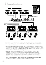
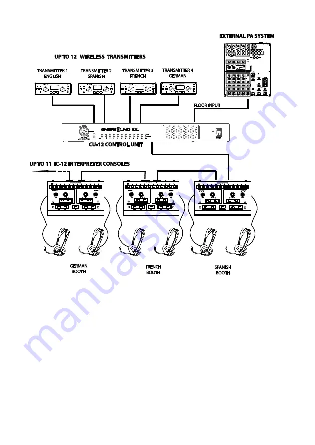
All consoles are connected via a D-Sub 25-pin cable in a daisy chain. On the rear panel of each IC-
12 interpreter console, there are two 25-pin D-Sub connectors, “INPUT” (Male) and “OUTPUT”
(Female).
1.
Connect the plug (male end) from the 25-pin cable to the Control Unit CU-12. Then connect the
socket (female end) from the 25-pin cable to the “INPUT” on the first Interpreter Console. After
that, connect the plug of the second 25-pin cable to the “OUTPUT” of the first Interpreter Console
and the socket to the “INPUT” of the next Interpreter Console.
2.
Follow the same procedure until all interpreter consoles are connected. A maximum of 11
interpreter units can be connected, allowing up to 22 interpreters to perform simultaneous
interpretation for a maximum of 11 target languages plus one floor (original) language. Each
Interpreter Console accommodates two interpreters to work in pairs for the same language
combination in the same booth.
Note: Extension cables can be used between Interpreter Consoles and/or Control Unit. Always
use 25-pin high quality cables provided or approved by the manufacturer.
MICROPHONE OUTPUT
CHANNEL
6
(Also called ORIGINAL INPUT)


