7
C048-784-30 R01, Rev. B (03/2021)
4.2
4.2 Mounting
Mounting
THIS PRODUCT MUST BE INSTALLED WITHIN A
RESTRICTED ACCESS LOCATION WHERE ACCESS IS
THROUGH THE USE OF A TOOL, LOCK AND KEY, OR
OTHER MEANS OF SECURITY, AND IS CONTROLLED
BY THE AUTHORITY RESPONSIBLE FOR THE
LOCATION� THIS PRODUCT MUST BE INSTALLED AND
MAINTAINED ONLY BY QUALIFIED TECHNICIANS�
SUITABLE FOR MOUNTING ON CONCRETE OR OTHER
NON-COMBUSTIBLE SURFACE ONLY�
NOTICE
:
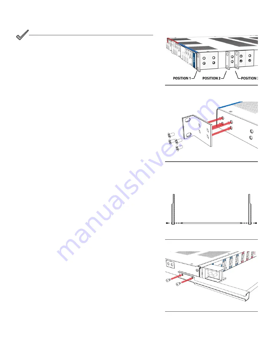
The TPA 250 Series fuse panel can be mounted in a front flush mount
configuration, a mid-mount forward configuration, or a mid-mount
rearward configuration. Depending on the desired configuration, attach
the mounting ears accordingly (see Figure 3)�
Step 1.
Attach the mounting ears with included 10-32 hardware (see
Figure 4)�
Step 2.
Select the equipment rack location for installation of the fuse
panel then secure the panel to the equipment rack by tightening
hardware into the mounting ears�
4.2.1
4.2.1 Optional Cable Lacing Bar Kit
Optional Cable Lacing Bar Kit
(C750-283-10)
(C750-283-10)
Step 1.
Install the cable lacing rod in between the left and right lacing
bar brackets by tightening a supplied 10-32 socket head screw
into each end of the threaded rod (see Figure 5)�
Step 2.
Attach the cable lacing bar assembly to the fuse panel by
tightening (2) 10-32 socket head screws per side into the
threaded holes located on each side of the fuse panel chassis
towards the rear (see Figure 6)�
Figure 3. Mounting ear positions
Figure 4. Mounting ears
(position 1 shown)
Figure 5. Cable lacing rod
Figure 6. Cable lacing bar assembly install


