8
C048-784-30 R01, Rev. B (03/2021)
4.2.2
4.2.2 Optional Rear Rack Support Kit
Optional Rear Rack Support Kit
(C750-277-10)
(C750-277-10)
An optional telescoping rear rack support kit is available to help secure
the panel to the rear of the equipment rack and to distribute panel weight
evenly� In addition to the standard lacing bar included with the TPA 250
Series fuse panel, a new lacing bar is included with this kit which can be
repositioned on any of the available lacing bar holes depending on the
depth of the equipment rack� Use a hex key to relocate the new lacing
bar if needed� See Appendix A for mechanical dimensions of rear rack
support kit�
Step 1.
Install the shorter cable lacing rod in between the left and right
lacing bar brackets by tightening a supplied 10-32 socket head
screw into each end of the threaded rod (see Figure 5 on Page 7)�
Step 2.
Attach the cable lacing bar assembly to the fuse panel by
tightening (2) 10-32 socket head screws per side into the
threaded holes located on each side of the fuse panel chassis
towards the rear (see Figure 6 on Page 7)�
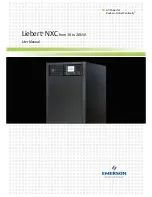
Step 3.
Install the longer cable lacing rod in between the left and right
lacing bar rear support rails by tightening a supplied 10-32 socket
head screw into each end of the threaded rod (see Figure 7)�
Multiple mounting holes are provided in the rails for optimal lacing
rod positioning�
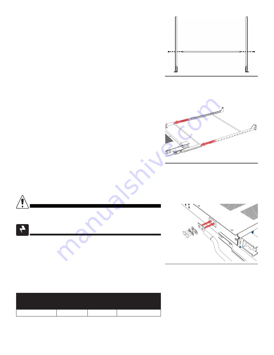
Step 4.
Slide the rails of the rear rack support assembly into the lacing
bar assembly (see Figure 8)�
Step 5.
Secure the mounting ears to equipment rack via the slotted holes
or threaded inserts�
4.3
4.3 Chassis Ground
Chassis Ground
DO NOT ENERGIZE THE PANEL BEFORE CHASSIS
GROUND IS CONNECTED�
CAUTION!
WARNING! ELECTRICAL HAZARD
DO NOT USE HARDWARE WITH A LENGTH EXCEEDING
3/4 INCH FOR CHASSIS GROUND CONNECTIONS�
The chassis ground is located on both sides of the panel� Two-hole
lug landing positions are provided� See table below for termination
information� A minimum of #4 AWG chassis ground cable is required�
IMPORTANT: Grounding hardware not included. A properly-sized
grounding conductor must be installed per NEC (250�122)�
Table 2.
Chassis Ground Termination Specifications
TERMINATION
TYPE
HOLE/STUD
SIZE
CENTER
TO CENTER
RECOMMENDED
TORQUE VALUE
Threaded insert
1/4 in�
5/8 in�
6.25 ft∙lbs
Step 1.
Secure the ground cable to the chassis by tightening 1/4 in�
hardware (see Figure 9)�
Figure 7. Cable lacing rod
(for rear rack support kit)
Figure 8. Rear support rails
(for rear rack support kit)
Figure 9. Chassis ground